Matrix integrated sequential magnetic attraction electric machine

a magnetic attraction electric machine and sequential technology, applied in the field of electric machines, can solve the problems of not providing the only suitable way to organize the matrix elements, and achieve the effect of reducing the output mechanical power, no energy waste, and high energy efficiency of the matrix machin

Active Publication Date: 2014-02-13
PRICOP JOHN +1
View PDF1 Cites 4 Cited by
  • Summary
  • Abstract
  • Description
  • Claims
  • Application Information

AI Technical Summary

Benefits of technology

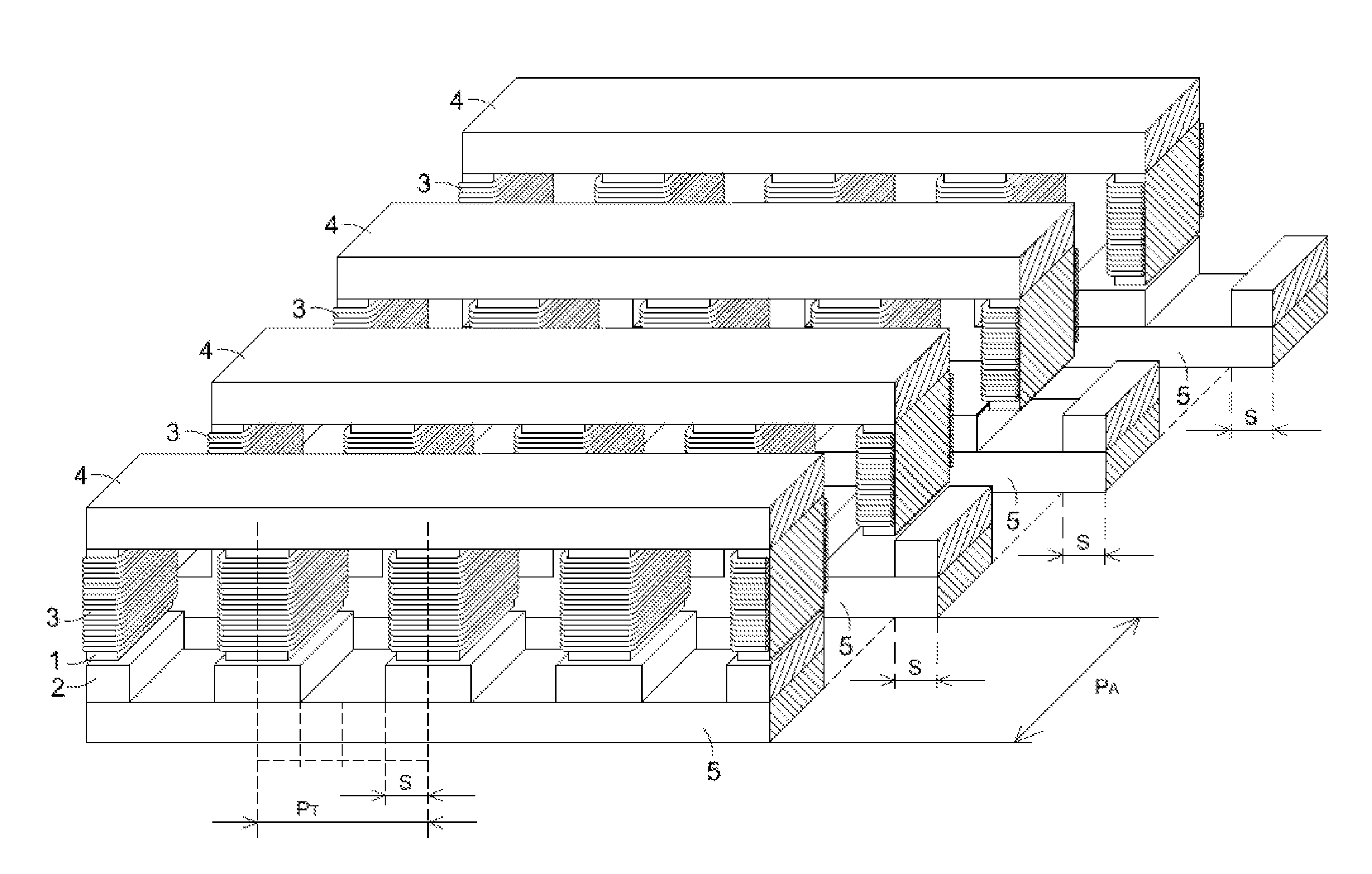
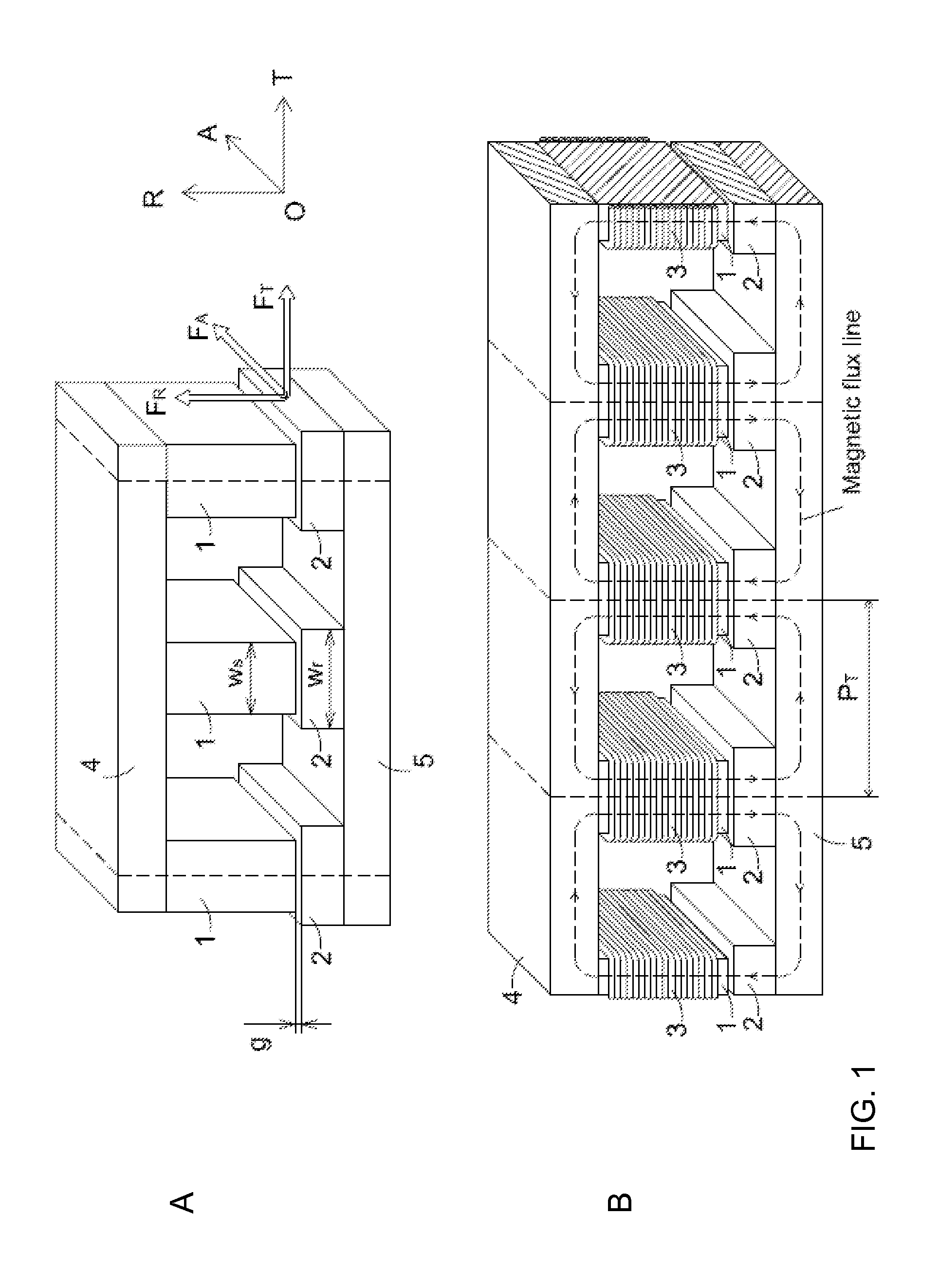
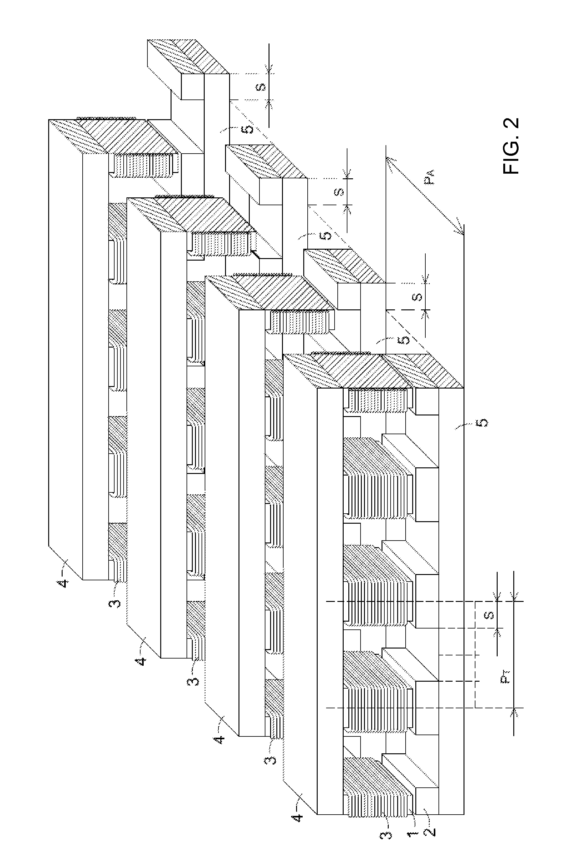
[0050]From the construction of the generic pole pair shown above, it is evident that the stator-rotor pole pairs are actually soft electromagnets (since no permanent magnets are used). In fully aligned positions of the generic pole pair, the generic electromagnet is equivalent to a closed magnetic circuit featuring a small air gap and fed by electric current pulses via the coil. In this position, the inductance of the coil has a maximum value LM. In fully unaligned positions, the generic electromagnet is equivalent to a closed magnetic circuit featuring a big air gap and fed by electric current pulses via the coil. In this position, the inductance of the coil has a minimum value Lm. The operation of the machine is based entirely on the cycling of the inductance of the generic electromagnet between the positions of minimum and maximum value as the rotor matrix moves the rotor poles (clockwise or counter-clockwise) with respect to the stator poles. When the electric current pulses are applied while the stator coil inductance is increasing, the matrix machine works in motoring mode (transforming electrical energy into mechanical energy). When the electric current pulses are applied while the stator coil inductance is decreasing, the matrix machine works in generation mode (transforming mechanical energy into electrical energy). If the electric pulses are applied when the stator coil inductance remains constant at value LM (which occurs when the moving rotor poles remain in full alignment with the stator poles due to a small overlap ratio), the machine cannot transform energy from one form to another. This region is used to recover the magnetic energy from the machine (stored as magnetic energy in the air gap) and send it back to the power supply via reverse stator current without incurring magnetic braking (which would reduce the output mechanical power).
[0051]In principle, the energy efficiency of a matrix machine is very high, especially in motoring mode (where it matters most), since there is no mechanism allowed to divert the input electrical energy into other uses than the production of mechanical torque impressed on the rotor. During operation in motoring mode, the energy drawn from the power supply is partially transformed into mechanical energy available to the load and partially accumulated as magnetic energy in the air gap. At the end of each discrete action, the magnetic energy stored in the air gap is recovered and sent back to the power supply via reverse current. In this way, no energy is wasted in the machine by means of a parasitic mechanism that diverts some of the input energy into a useless form of energy that cannot be recovered. However, according to the second law of thermodynamics, in the real world there is no process that can be carried out with perfect efficiency, so the matrix machine will indeed waste small amounts of energy during operation. A part of the waste energy is dissipated as heat in the coils due to the electrical resistance of the magnet wire when the current pulses are applied (resistive losses). Another part is dissipated as heat in the magnetic core due to magnetization (hysteresis losses) and induction (eddy current losses) when the electric current pulses in the coils are switched on and off at high frequency (core losses). The magnitude of the core losses is proportional to the volume of the magnetic paths. Since the matrix machine uses exclusively the energy-efficient short path for all stator-rotor pole pairs, the core losses are minimized by design. Yet another part is dissipated as heat in the bearings due to the mechanical friction between their moving parts, especiall...

Problems solved by technology

However, these readily apparent options do not provide the only suitable ways to organize the matrix elem...

Method used


Image

  • Matrix integrated sequential magnetic attraction electric machine
  • Matrix integrated sequential magnetic attraction electric machine
  • Matrix integrated sequential magnetic attraction electric machine

Examples


Embodiment Construction

[0040]The matrix machine presented here can be operated randomly in either motoring or generation mode simply by selecting the appropriate scanning algorithm. As shown previously, the essential difference between the motoring and generation modes of operation consists in the sign of inductance slope during the activity of the generic stator-rotor pole pair. If the inductance slope is positive, the machine works in motoring mode. Conversely, if the inductance slope is negative, the machine works in generation mode. The scanning algorithms for the motoring and generation modes are similar, but not identical. For this reason, the logic unit needs a non-volatile random access memory module (shown in the block diagram in FIG. 13) to store the various scanning algorithms for each specific operation mode.

[0041]The active elements of the matrix machine can be operated independently (in which case each active element is connected to a separate power converter output), or can be grouped in su...


PUM


Abstract

The invention discloses a reciprocal radial field electric machine based on the soft magnetic attraction principle, characterized by a plurality of active elements organized as a bi-dimensional cylindrical machine matrix and fed sequentially by an external power converter in order to derive a motoring or generation effect. The machine is comprised of a fixed stator matrix featuring salient poles and electrical coils, and a mobile rotor matrix featuring salient poles. The machine works on the principle of time integration of the discrete actions performed by its active elements. The bi-dimensional matrix organization of the active elements and the algorithms of their activation in both motoring and generation modes are key features for the functional cohesion of the machine. The design of this machine is based on a unique digital modeling method developed by the inventors, using exclusively the matrix calculus adapted to cylindrical matrices.

Description

BACKGROUND OF THE INVENTION[0001]1. Field of the Invention[0002]The invention pertains generally to electric machines. More specifically, the invention relates to the class of electric machines using no permanent magnets and operating solely on the principle of magnetic attraction between an array of soft magnetic parts that are mounted on a fixed base (usually referred to as “stator”) and another array of soft magnetic parts that can move with respect to the fixed base (usually referred to as “rotor” or “translator”), where only the array on the fixed base contains electrical windings connected to a power converter and controlled by a logic unit.[0003]In order to ascertain accurately the place of the machine that constitutes the subject of this invention within the aforementioned class of machines, a brief exposé on the specificity of these machines is presented in this section.[0004]This class of machines has two essential features: it employs no permanent magnets in either the st...

Claims


Application Information

Patent Timeline
IPC IPC(8): H02P6/14H02P6/08H02K19/10H02K21/12
CPCH02K19/24H02K19/103H02P25/08
Inventor PRICOP, JOHNCARVALHEIRO, CARLOS MANUEL
Owner PRICOP JOHN
Why Eureka
Try Eureka