Lighting device

a technology of lighting device and light source, which is applied in the field of lighting device, can solve the problems of difficulty in preparing imaging bodies having a variety of patterns beforehand, and achieve the effects of improving the degree of freedom of design of lighting device, improving video visibility, and improving the degree of freedom of design

Active Publication Date: 2014-02-13
SEIKO EPSON CORP
View PDF5 Cites 56 Cited by
  • Summary
  • Abstract
  • Description
  • Claims
  • Application Information

AI Technical Summary

Benefits of technology

[0010]Another aspect of the invention is directed to the light device, wherein the lighting unit further includes: a light transmitting section provided in a position where the video light from the video forming section is irradiated, a transparent state and a non-transparent state of the light transmitting section being switched according to presence or absence of application of a voltage; and a control section configured to control the voltage applied to the light transmitting section according to presence or absence of projection of the video light from the video forming section. With this configuration, whereas the light for lighting is scattered and radiated, the video is clearly reflected on the enclosure. Therefore, visibility of the video is improved even when the light is used for lighting.
[0011]Still another aspect of the invention is directed to the lighting device, wherein the lighting unit further includes a projecting-direction converting section configured to change a direction of the video light projected by the video forming section and project the video light on the enclosure. With this configuration, limitation on a positional relation between the lighting unit and the enclosure is relaxed and a degree of freedom of design of the lighting device is improved.
[0012]Yet another aspect of the invention is directed to the lighting device, wherein the light source section for lighting and the light source section for video formation are configured separately, and the lighting unit includes a partition wall section configured to partition a first space in which the light source section for video formation and the video forming section are housed and a second space in which the light source section for lighting is housed. With this configuration, a function for lighting and a function for forming a video work independently from each other. Further, since light radiated as a video is clearly reflected without mixing in light radiated as lighting, visibility of the video is improved.
[0013]Still yet another aspect of the invention is directed to the lighting device, wherein the video forming section projects the video light in a direction different from a direction of light radiated as lighting by the light source section for lighting. With this configuration, since a region where the light projected as the video is reflected on the enclosure and a region where the light is reflected on the enclosure as lighting are different, visibility of the video is improved.
[0014]Further another aspect of the invention is directed to the lighting device, wherein the lighting device further includes a control section configured to switch lighting or extinguishing of the light source section for lighting or a video signal supplied to the video forming section. With this configuration, since a unit allowing the user to switch presence or absence of radiation of light and a video signal to be supplied is given to the user, convenience is improved.
[0015]Still further another aspect of the invention is directed to the lighting device, wherein the lighting device further includes a housing section configured to detachably house a communication device that accumulates a video signal, and the control section switches whether the video signal is output from the communication device to the video forming section. With this configuration, since the user can select the video signal accumulated by the communication device, convenience is improved.

Problems solved by technology

Therefore, it is difficult to prepare imaging bodies having a variety of patterns beforehand.

Method used


Image

  • Lighting device
  • Lighting device
  • Lighting device

Examples


first embodiment

[0033]An embodiment of the invention is explained below with reference to the accompanying drawings.

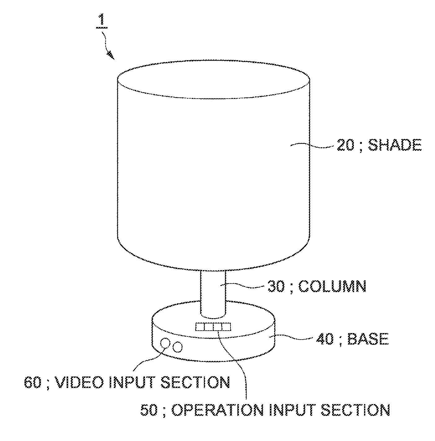
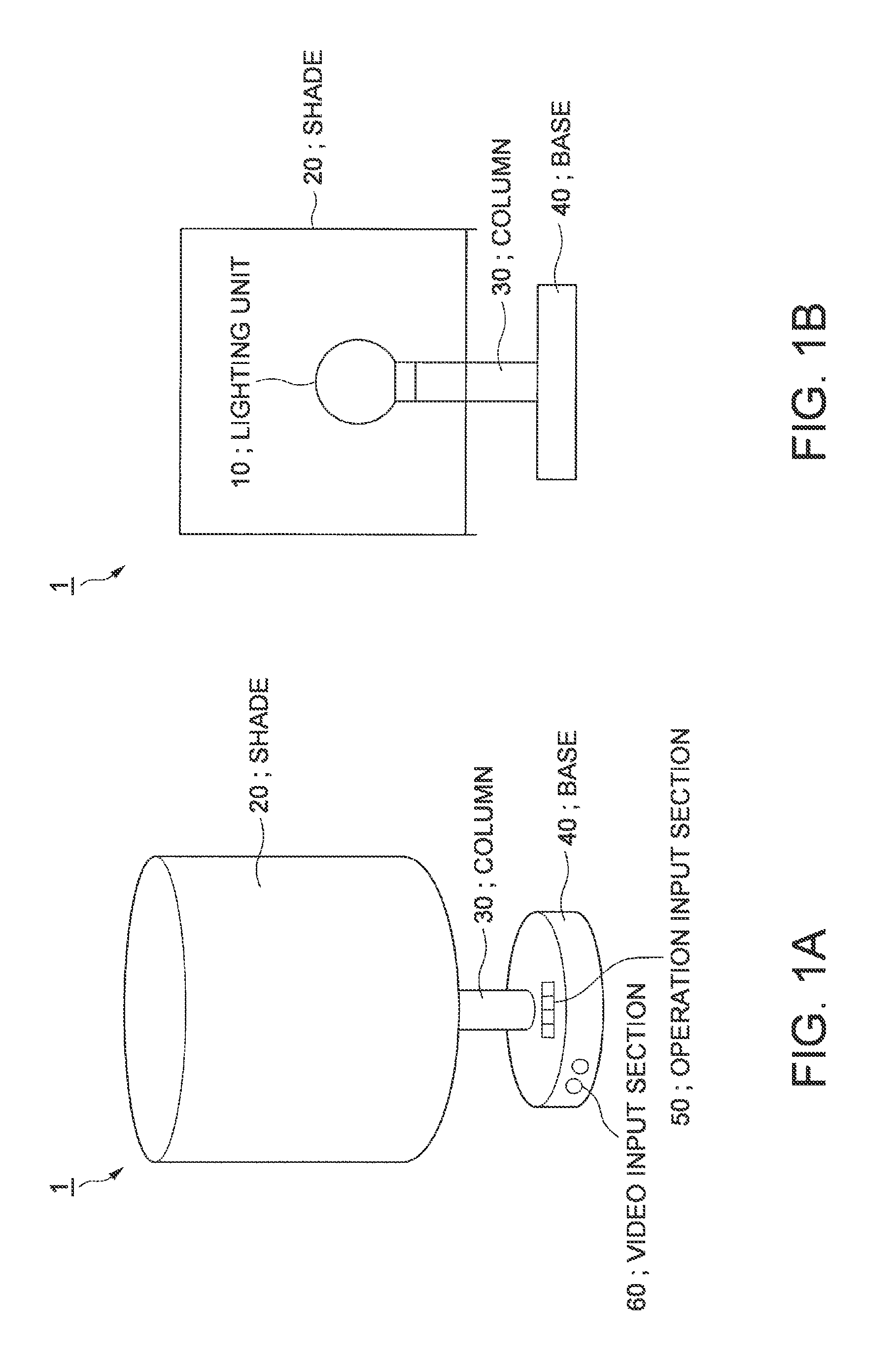
[0034]FIGS. 1A and 1B are external views showing an external appearance of a lighting device 1 according to this embodiment.

[0035]The lighting device 1 includes a lighting unit 10, a shade (an enclosure) 20, a column 30, a base 40, an operation input section 50, and a video input section 60.

[0036]FIG. 1A is a perspective view showing a side of the lighting device 1.

[0037]The shade 20 has, for example, a cylindrical shape. The upper surface of the shade 20 is opened and the side surface of the shade 20 surrounds the lighting unit 10. The shade 20 transmits parts of light and a video radiated by the lighting unit 10 set on the inside of the shade 20. The material of the shade 20 is not always limited to a transparent material (e.g., polyester) and may be a semitransparent material or may be a material in which fine light transmitting holes are dispersed (e.g., paper or cloth).

[0038]The ...

second embodiment

[0167]A second embodiment of the invention is explained. Components same as the components in the first embodiment are denoted by the same reference numerals and signs. The explanation in the first embodiment applies to the second embodiment.

[0168]FIG. 15 is a schematic diagram showing the configuration of a lighting device 2 according to this embodiment.

[0169]The lighting device 2 according to this embodiment includes an input / output processing section 220. The input / output processing section 220 includes a housing section 250 configured to detachably house a communication device 300. Like the operation input section 50, the input / output processing section 220 receives, using the communication device 300, operation inputs related to presence or absence of lighting of the lighting section 190, selection of a video signal, and reproduction of a video and a stop of the reproduction of the video. When the communication device 300 is housed in the housing section 250, a control section ...


PUM


Abstract

A lighting device includes a lighting unit and an enclosure (e.g., a shade) configured to cover a part or all of the periphery of the lighting unit and transmit light from the lighting unit. The lighting unit includes a light source section for lighting configured to radiate light and a video forming section configured to form video light obtained by modulating, on the basis of video information, light from a light source section for video formation configured integrally with or separately from the light source section for lighting and project the video light on the enclosure.

Description

[0001]The entire disclosure of Japanese Patent Application No. 2012-178146, filed Aug. 10, 2012 is expressly incorporated by reference herein.BACKGROUND[0002]1. Technical Field[0003]The present invention relates to a lighting device having a lighting function and a video displaying function.[0004]2. Related Art[0005]There has been known a lighting device that reflects a pattern. For example, a lighting device for decoration described in JP-A-2006-302727 (Patent Literature 1) includes an imaging body having optical transparency and provided with a pattern for imaging on a curved surface, a light source configured to obliquely irradiate light toward the imaging body, and a cover provided with an opening section through which the light irradiated from the light source and transmitted through the imaging body is transmitted toward a shadow picture projection surface.[0006]However, in the lighting device for decoration described in Patent Literature 1, to change a video to be projected, ...

Claims


Application Information

Patent Timeline
Patent Type & Authority Applications(United States)
IPC IPC(8): F21V33/00
CPCF21V33/0052G03B21/10G03B21/145H04N9/3141
Inventor KASUGA, HIROFUMI
Owner SEIKO EPSON CORP
Why Eureka
Try Eureka