Window condensation control

a technology for controlling condensation and windows, applied in ventilation systems, lighting and heating apparatus, heating types, etc., can solve the problems of deterioration of wood, visibility through windows, and relatively cooler air not holding as much moistur

Inactive Publication Date: 2014-02-13
BARTMANN JOSEPH J
View PDF8 Cites 18 Cited by
  • Summary
  • Abstract
  • Description
  • Claims
  • Application Information

AI Technical Summary

Benefits of technology

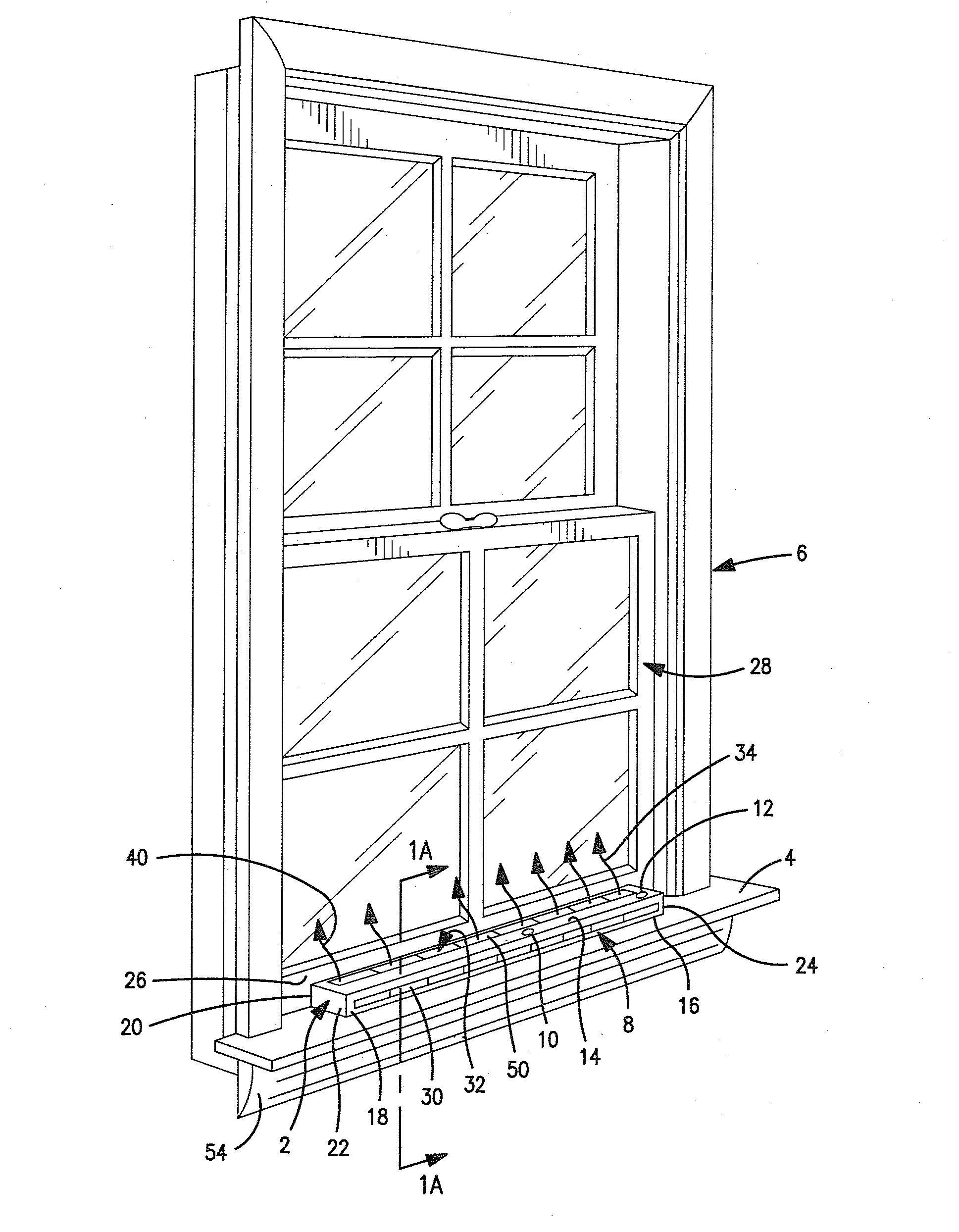
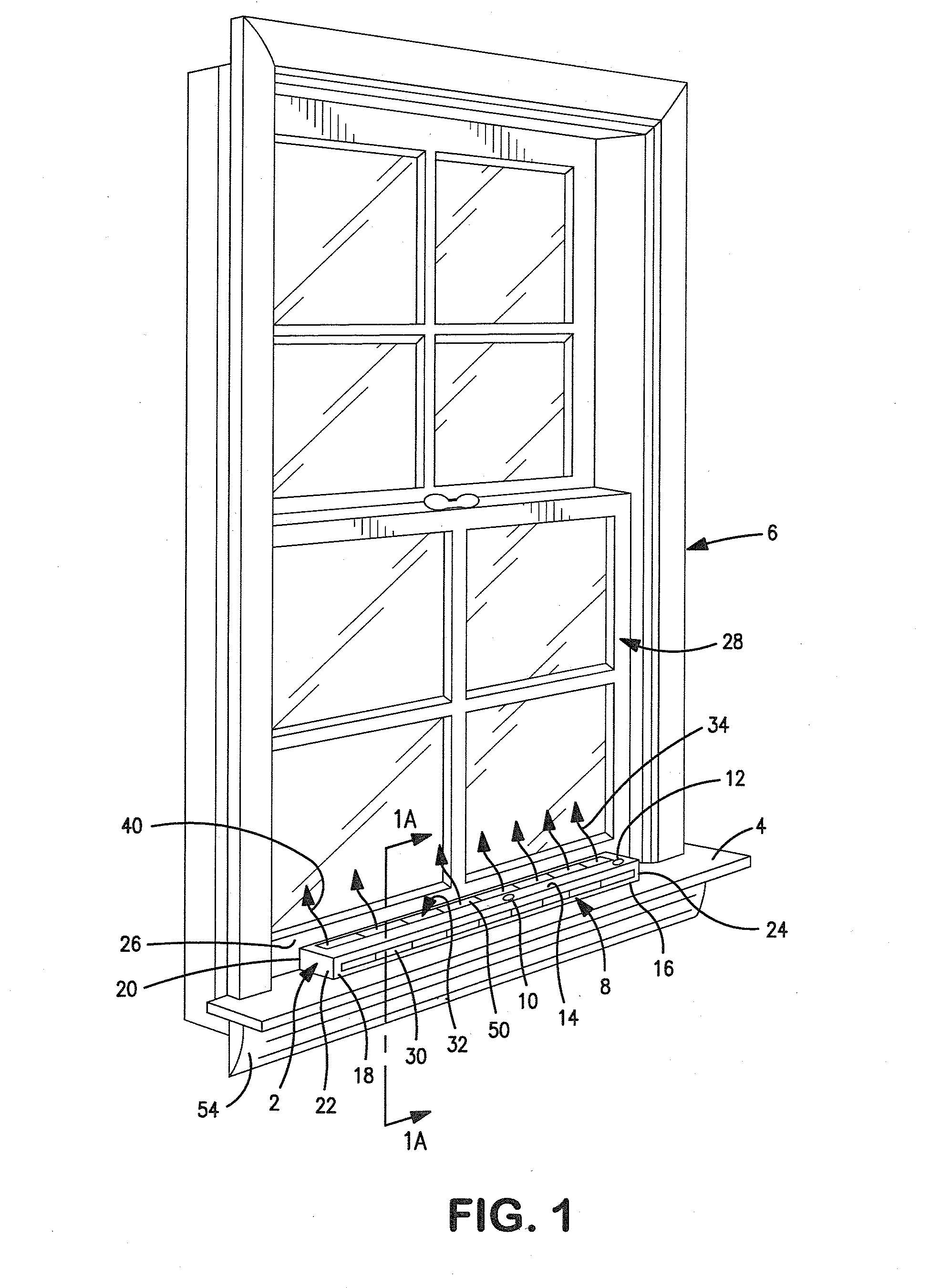
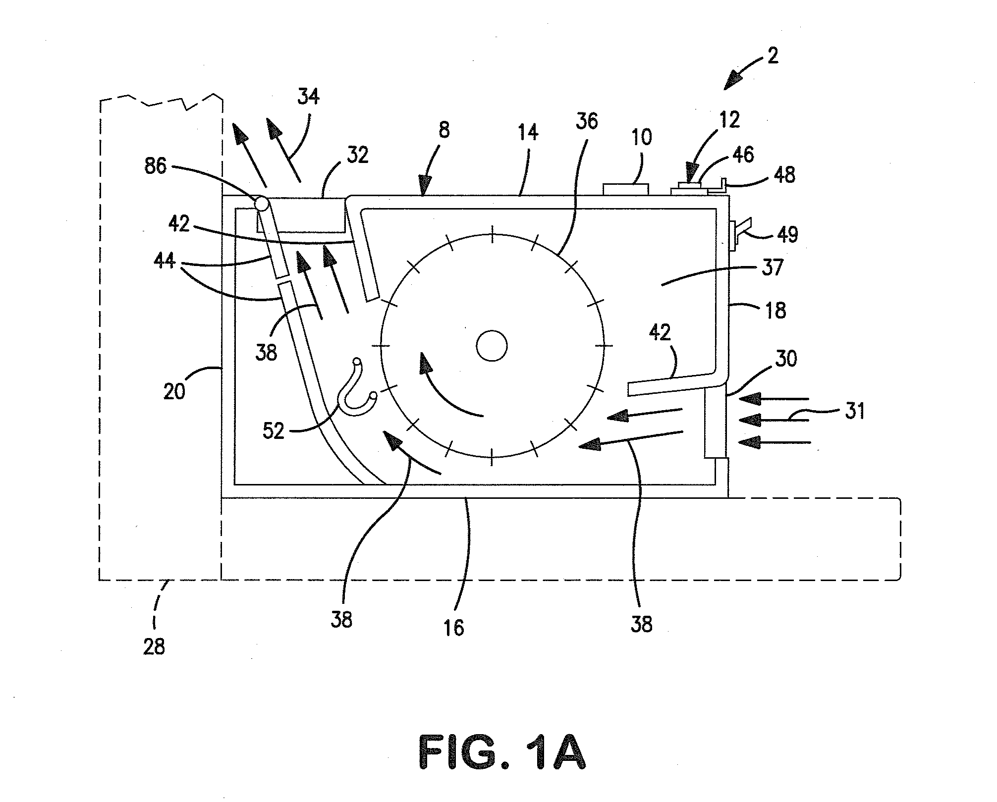
[0047]In some embodiments, the window further comprises a first condensation sensor sensing condensation on the window proximate the first leg and a second condensation sensor sensing condensation on the window proximate the second leg, and a controller receiving input from both of the first and second sensors, the controller sending a first set of control signals to the first blower and the first heater in the first leg in response to input from the first sensor, and sending a second set of control signals to the second blower and the second heater in the second leg in response to input from the second sensor.

Problems solved by technology

Thus, all other factors being equal, relatively cooler air cannot hold as much moisture as relatively warmer air.
Condensation thus creates a first problem of obscuring, or partially obscuring, visibility through the window.
As the water remains on the sill and sash for extended periods of time, the water penetrates the finish coating on the wood and deteriorates the wood substrate of the window sash frame and the window sill thus creating a second problem of causing deterioration of the wood which serves as the substrate for the sash and / or the window frame.
In addition, the falling curtain of cooler air creates a third problem in that the cool air falls close to the floor and creates a cold draft close to the floor, which can result in thermal discomfort to people in the room as they experience “cold feet”.
Given the above scenario, water may remain on part of the sash frame and the sill of the window frame for prolonged periods of time.
Commonly-used protective coatings are effective to prevent penetration to the underlying wood substrate for short periods of time, but are not effective to prevent penetration to the underlying wood when the water is present on the coated surface for prolonged periods of time.
The wetted underlying wood is then vulnerable to attack by the various organisms which feed on wetted cellulose in the wood, causing deterioration of the structural capacity of the wood.
Over time, the structural integrity of the wood is sufficiently degraded by such attack that the barrier function of the window is compromised such that the window must be replaced.
In addition, water penetration and persistent residence of water in / on the wood can and may support growth of mold and / or mildew in the wood and in the wall structure surrounding the window installation site.
This also ruins the wall and causes serious health issues to occupants of the building.
Condensed water on windows has long been recognized as a problem, both in terms of obscuring visibility through the window and in terms of deterioration of the window sill and the sash frame.

Method used


Image

  • Window condensation control
  • Window condensation control
  • Window condensation control

Examples


example

[0160]FIGS. 8A and 8B illustrate a test set-up which was used for testing an air handler of the invention similar to the one described with respect to FIGS. 7 and 8. FIG. 8A shows a cross-section of the test set-up. FIG. 8B shows the same test set-up in front elevation view. The cross-section of FIG. 8A reveals a conventional double-hung window mounted in a conventional sash, and held in typical 6-inch nominal framing. The outside of the window frame is boxed in and filled with conventional fiberglass insulation, thus to simulate a conventional window installation in typical residential construction.

[0161]On the rear of the window structure is mounted a rear closure panel 118 which closes off the rear of the window from the ambient environment, thus creating a chilling cavity 120.

[0162]The window unit as tested was 2 feet wide by 3 feet tall. U-values for the upper and lower glazings 122, 124 were 0.35W / m*K.

[0163]Before start of the tests, the rear surface of the window frame was co...


PUM


Abstract

A window air handler mounted to a window admits a supply of air from inside the building at the top of the window and blows that air downwardly and onto the inner surface of the window. A leg depends downwardly from an air inlet, to air outlets which express the air across the width of the window. The air can be ambient, or heated. The so-expressed air warms the glass enough to avoid condensation on the glass, or to remove and absorb condensation which has already formed on the glass. The air handler can comprise a single leg extending down along one side of the window or two legs extending down along opposing sides of the window. Air inlets are proximate the tops of the legs, and air outlets are below the inlets.

Description

CROSS-REFERENCE TO RELATED APPLICATIONS[0001]This application is a Continuation-In-Part of U.S. Non-Provisional Application 12 / 386,700, filed Apr. 21, 2009, which is a Non-Provisional Patent Application of Provisional Application 61 / 124,938, filed Apr. 21, 2008, the complete disclosures of all of which are incorporated herein by reference, in their entireties.BACKGROUND[0002]This invention relates generally to the problem of moisture vapor in the air in a building, and wherein the moisture vapor condenses on the building windows when the temperature outside the building is substantially colder than the temperature inside the building. It is important to maintain a certain level of humidity in the air in a so-warmed building thus to avoid drying out of sinuses and other internal and external body surfaces of people who occupy the building. For example, a relative humidity of about 30% is typically desired during winter weather in the northern part of the temperate zone.[0003]Absolute...

Claims


Application Information

Patent Timeline
Patent Type & Authority Applications(United States)
IPC IPC(8): E06B7/12F24F7/06
CPCF24F7/065E06B7/12E06B7/10F24F13/18E06B2007/023F24F2013/221H05B1/028F24F11/30F24F2110/20F24F11/76
Inventor BARTMANN, JOSEPH J.
Owner BARTMANN JOSEPH J
Why Eureka
Try Eureka