Reactive shoe

a technology of midsole and flex, which is applied in the direction of uppers, insoles, domestic applications, etc., can solve the problems of insignificant influence of conventional designs, and achieve the effect of reducing thickness, smoother and more efficient running experien

Inactive Publication Date: 2014-02-20
DASHAMERICA
View PDF11 Cites 43 Cited by
  • Summary
  • Abstract
  • Description
  • Claims
  • Application Information

AI Technical Summary

Benefits of technology

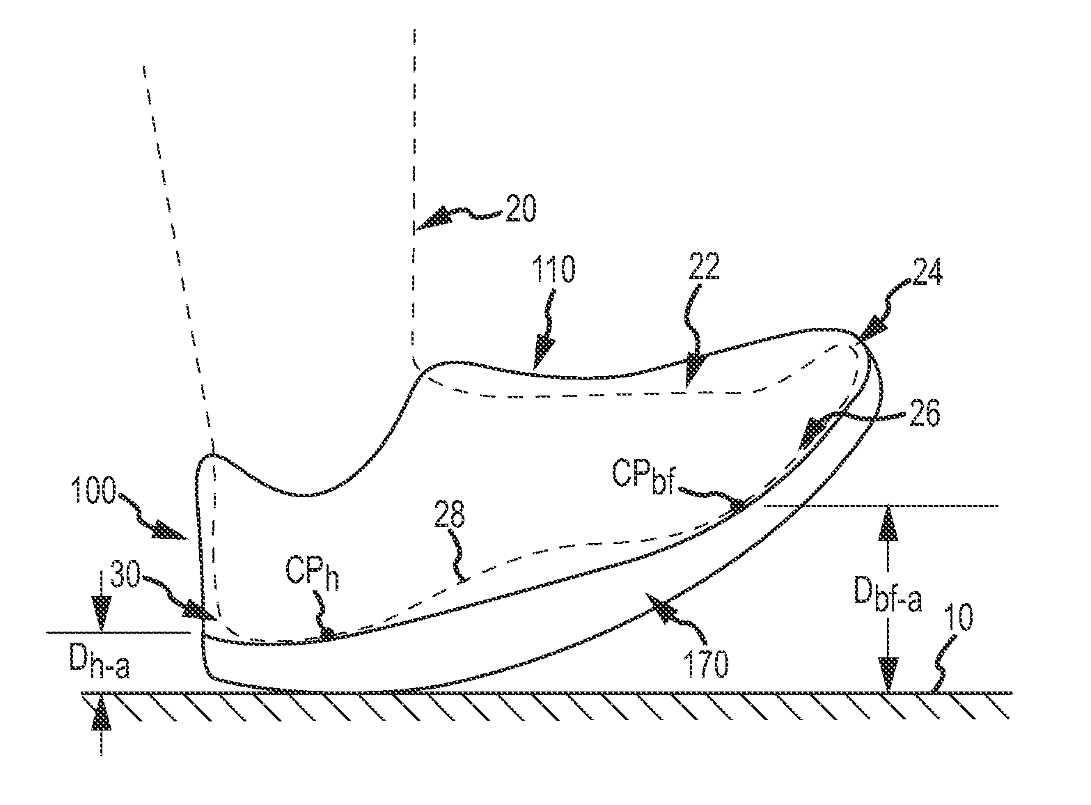
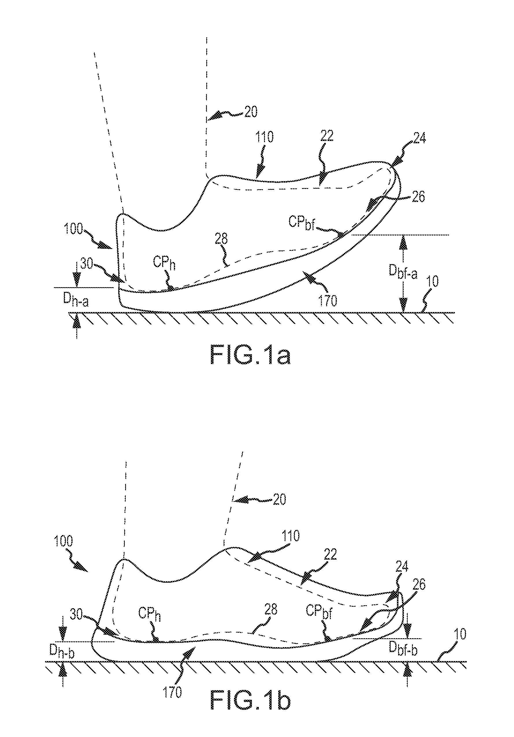
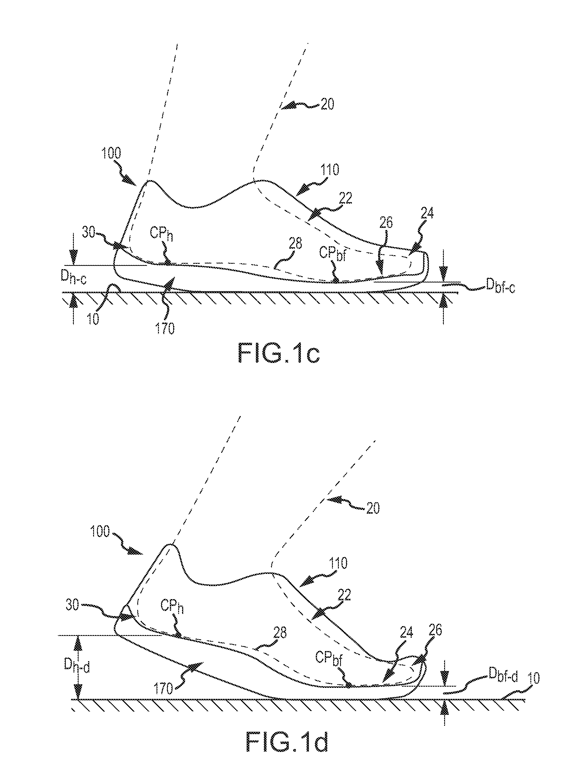
[0011]It is one aspect of the present invention to provide an athletic shoe with a reactive midsole that provides an increasing offset between a heel center of pressure and a ball-of-foot center of pressure between the loading and a toe off gait phases. Such a midsole creates a dynamic offset and, among other things, provides a smoother and more efficient running experience. In some embodiments, the midsole comprises a first portion adjacent the heel and a second portion, interconnected to the first, of generally decreasing thickness, in which the first portion is of equal or less total distance of the longitudinal axis of the midsole. In some embodiments, a foot center of pressure imparted to the midsole continuously increases between the loading gait phase and the toe off gait phase.
[0012]Although many of the embodiments are focused on athletic footwear, other applications are available. Such applications include activities in which one or more of increased footwear performance, increased athletic performance and increased comfort is desired.
[0030]The present disclosure, in various embodiments, configurations, or aspects, includes components, methods, processes, systems and / or apparatus substantially as depicted and described herein, including various aspects embodiments, configurations, sub-combinations, and subsets thereof. Those of skill in the art will understand how to make and use the various aspects, embodiments, configurations, sub-combinations, and subsets of the present disclosure after understanding the disclosure. The present disclosure, in various aspects, embodiments, and configurations, includes providing devices and processes in the absence of items not depicted and / or described herein or in various aspects, embodiments, or configurations hereof, including in the absence of such items as may have been used in previous devices or processes, e.g., for improving performance, achieving ease and\or reducing cost of implementation.

Problems solved by technology

However, the conventional designs do not appreciably if at all influence the loading dynamics of a runner's heel center of pressure and a ball-of-foot center of pressure, or combinations thereof, during the phases of engagement with the ground.

Method used


Image

  • Reactive shoe
  • Reactive shoe
  • Reactive shoe

Examples


example

[0095]Without intending to limit the scope of the invention, Example A1-A13 depicts one example construction of one embodiment of the invention in drawings each to scale. Dimensions are in millimeters.

[0096]Examples A1-A3 depicts respective lateral, bottom, and medial views of the outsole / midsole portion of one embodiment of the invention. Examples A5-A6 depict respective toe and heel views of the outsole / midsole of Examples A1-3. Example A4 depicts a generally longitudinal cross-sectional view along axis Section A-A′ of Example A2. Examples A7-A12 depict sequential cross-sectional views of insole / midsole of Examples A1-3.

[0097]Note different materials and different geometries of Examples A7-A12. For example, the material of upper left to lower right cross-section markings (the dominant material of Example A7) is of a first material (here, CMEVA), the material with lower left to upper right cross-section markings (the mid-upper portion of Example A7) is of a second material (here, V...


PUM


Abstract

This invention relates generally to footwear and methods for making the same, and more particularly to an athletic shoe with a reactive midsole. In one aspect of the invention, the midsole provides a continuously increasing offset between a heel center of pressure and a ball-of-foot center of pressure between the loading and a toe off gait phases.

Description

CROSS REFERENCE TO RELATED APPLICATIONS[0001]This application claims the benefit of U.S. Provisional Patent Application No. 61 / 684,563, entitled “REACTIVE SHOE” filed on Aug. 17, 2012, the entire disclosure of which is incorporated by reference herein. This application also cross-references the following U.S. Design patent application Ser. Nos. 29 / 428,044, 29 / 428,045, 29 / 428,047, 29 / 428,049, 29 / 428,051 and 29 / 428,052, all filed Jul. 25, 2012 and all entitled “Shoe Sole,” the entire disclosures of which are all incorporated by reference herein.FIELD[0002]This disclosure relates to a midsole for footwear, more particularly to a reactive midsole having a dynamic offset.BACKGROUND[0003]Athletic footwear ideally provides protection from injury while enhancing performance. Generally, athletic footwear comprises an upper portion and a sole portion. The upper portion at minimum secures the footwear to the user's foot and attaches to the sole. The sole traditionally comprises a midsole and a...

Claims


Application Information

Patent Timeline
Patent Type & Authority Applications(United States)
IPC IPC(8): A43B7/14
CPCA43B7/14A43B13/145A43B13/187A43B13/223
Inventor TUCKER, SCOTTTHOMPSON, MICHAELREHFELDT, KEEGAN
Owner DASHAMERICA
Why Eureka
Try Eureka