
Motor control device, motor control method, and image forming apparatus

a technology of motor control and control method, which is applied in the direction of motor/generator/converter stopper, electronic commutator, dynamo-electric converter control, etc., can solve the problem that the drive state of the dc motor controlled in the position holding state may be detected erroneously as being in the lock state, and damage to the switching devi

Active Publication Date: 2014-02-20
RICOH KK
View PDF4 Cites 12 Cited by
  • Summary
  • Abstract
  • Description
  • Claims
  • Application Information

AI Technical Summary

Benefits of technology

The present invention aims to solve problems in conventional motor control technology. The invention includes a motor control device and method that supplies a constant period of motor drive based on a drive control signal. When the motor reaches a certain threshold of state change, the drive control signal is shut off and the motor is allowed to rest for a predetermined period. This allows for smoother motor control and better accuracy. The motor control device includes a setting unit to set the motor's rotational direction, a control unit to alternately set the rotational direction, and a generating unit to generate the drive control signal. Overall, this invention improves motor control accuracy and efficiency.

Problems solved by technology

This may cause damage to the switching device.
There is a problem, however, in that if the control is performed without determining whether the drive state of the DC motor is the normal drive state or the position holding state, the drive state of the DC motor controlled in the position holding state may be detected erroneously as being in the lock state.

Method used


Image

  • Motor control device, motor control method, and image forming apparatus
  • Motor control device, motor control method, and image forming apparatus
  • Motor control device, motor control method, and image forming apparatus

Examples


Embodiment Construction

[0027]The following describes an embodiment of a motor control device, a motor control method, and an image forming apparatus in detail with reference to the accompanying drawings.

[0028]Structure of Motor Control System according to Embodiment

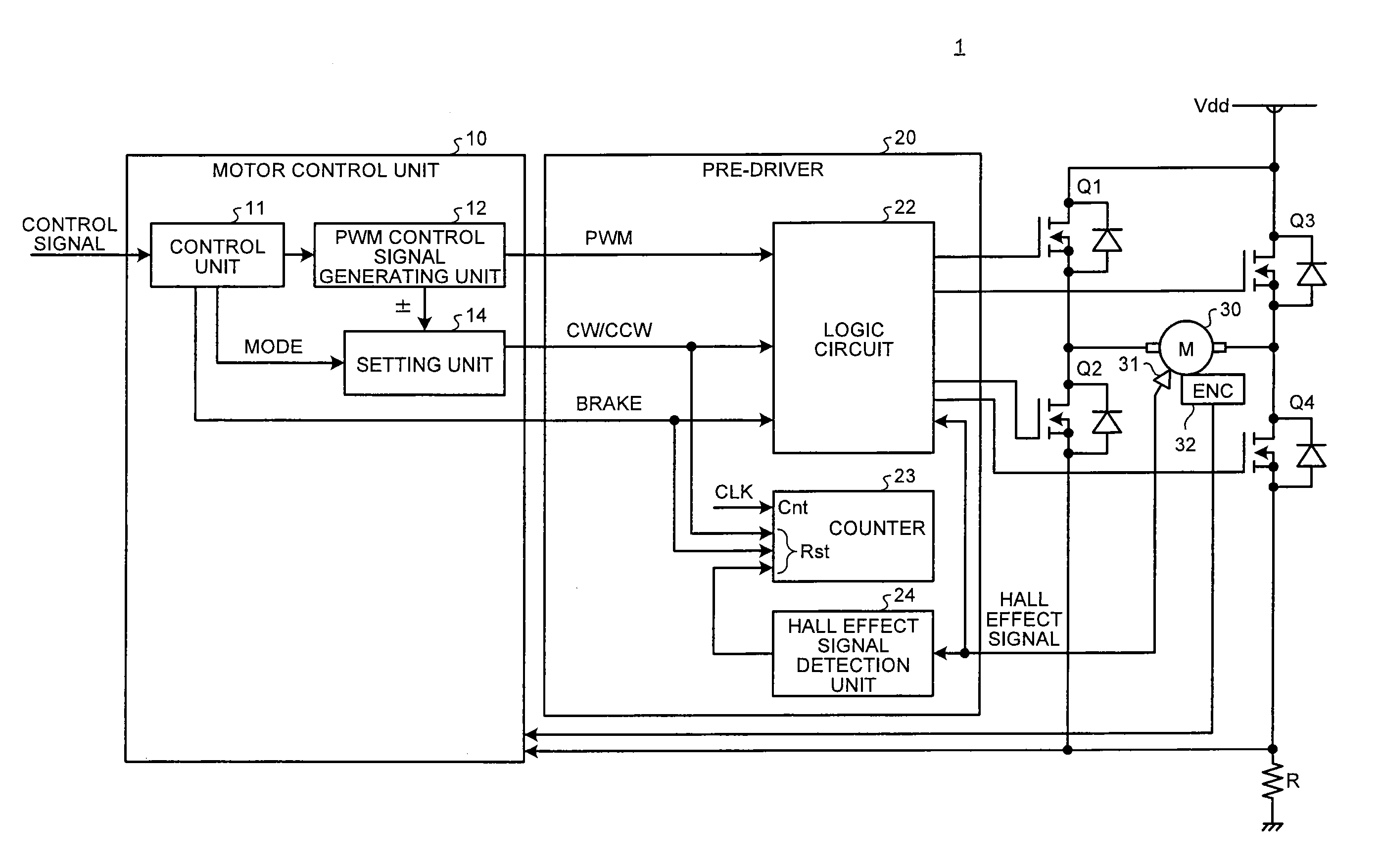
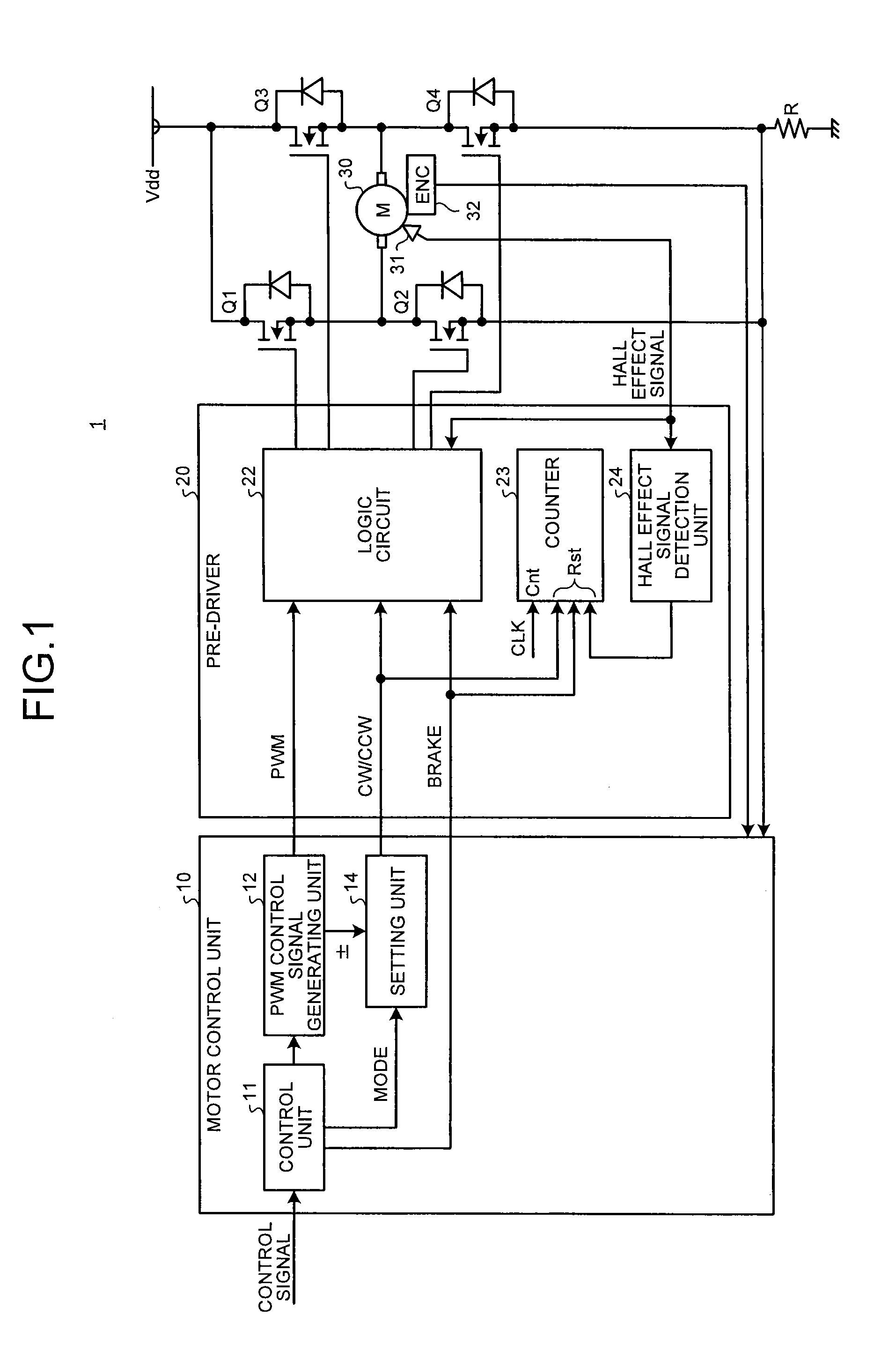
[0029]FIG. 1 illustrates an exemplary structure of a motor control system 1 according to an embodiment. The motor control system 1 according to the embodiment is included in a total control unit (not illustrated) having a controller that totally controls the operation of an apparatus (e.g. an image forming apparatus) to which the motor control system 1 is applied. In the motor control system 1, a pre-driver 20 outputs a motor drive signal based on a drive control signal and an operation control signal generated by a motor control unit 10. The motor drive signal drives a motor 30 to control the rotation of the motor 30.

[0030]In the embodiment, the motor 30 is a brushless direct current (DC) motor, and the motor drive signal is a pulse width modu...


PUM


Abstract

A motor control device supplies a drive control signal to a drive circuit that drives a motor at a constant period using a motor drive signal based on the drive control signal, and shuts off the motor drive signal when a count value counted by a counter that reset the count value if a state of the motor changes exceeds a threshold corresponding to a plurality of driving periods of the motor. The motor control device includes: a control unit that controls a setting unit to set a rotational direction of the motor to a first rotational direction and a second rotational direction reverse to the first rotational direction at the constant period alternately, when a drive mode of the motor is a position holding mode to drive the motor so as to hold a rotational position of the motor.

Description

CROSS-REFERENCE TO RELATED APPLICATIONS[0001]The present application claims priority to and incorporates by reference the entire contents of Japanese Patent Application No. 2012-181211 filed in Japan on Aug. 17, 2012.BACKGROUND OF THE INVENTION[0002]1. Field of the Invention[0003]The present invention relates to a motor control device that controls a motor, a motor control method, and an image forming apparatus.[0004]2. Description of the Related Art[0005]Image forming apparatuses such as a printer have been known that form images onto the sheets conveyed by a sheet conveying unit with an image forming unit using the inkjet printing structure or the electrophotography.[0006]Stepping motors have been used as a driving unit for driving the sheet conveying unit. Technologies using a direct current (DC) motor are also widely known in place of technologies using the stepping motors. When using a DC motor, the rotational speed of the DC motor is detected and feedback control is performed ...

Claims


Application Information

Patent Timeline
Patent Type & Authority Applications(United States)
IPC IPC(8): H02P6/08H02P6/06H02P6/12H02P6/16
CPCH02P6/08H02P3/025B41J19/00H02P6/30
Inventor ISHIZUKA, NATSUKOMURATA, TAKUYAKIGUCHI, HIROYUKISEKI, TAKEO
Owner RICOH KK
Learn More