Frame Structure for a Multi-Hop Wireless System

a wireless system and frame structure technology, applied in the field of wireless transmission systems, can solve the problems of increasing the complexity of equipment at a relay station, unable to meet the needs of terminals, and difficult or impossible to achieve high-level isolation between the receive path and the transmit path in many relay station installations, so as to reduce the interference within the network

Active Publication Date: 2014-02-20
APPLE INC
View PDF5 Cites 33 Cited by
  • Summary
  • Abstract
  • Description
  • Claims
  • Application Information

AI Technical Summary

Benefits of technology

[0014]Providing the second set of frame control information at a different position within the downlink sub-frame has an advantage that a relay station served by the base station does not need to receive frame control information at the same time as it transmits frame control information. A relay station is able to transmit a downlink sub-frame which includes a set of frame control information in the same position as that transmitted from the base station, typically at the start of the downlink sub-frame. This allows the relay station to appear to a terminal in the same manner as a base station. The relay station receives the second set of frame control information from the base station at a separate time during the downlink sub-frame. The invention is especially useful in a wireless network in which the downlink transmissions of a base station and a relay station are synchronized to one another and where the downlink transmissions of a base station and relay station occupy the same frequency bearer, or closely spaced frequency bearers.
[0020]It has been realized that there are situations in which it is not always necessary for the base station to transmit both the first and second sets of frame control information and in these situations the base station can adapt the content of the downlink sub-frame. In the case where the network does not have any relay stations which form part of a multi-hop path having an even number of hops, the base station does not need to transmit the second set of frame control information. In the case where all of the terminals in the network are served via relay stations which form part of a multi-hop path having an even number of hops, the base station does not need to transmit the first set of frame control information. The base station can either reallocate the space within the downlink sub-frame which would have been occupied by the first set of frame control information to other downlink traffic, or it can simply not transmit within that part of the downlink sub-frame, which has an advantage in reducing interference within the network.

Problems solved by technology

It has been realized that situations arise where terminals cannot be adequately served by a direct path to a base station.
A multi-hop transmission path may be needed when a single hop transmission path does not offer a sufficient quality.
This will increase the complexity of equipment at a relay station as it requires a relay station to have receiver equipment which can operate at the same time as the relay station is transmitting data.
It also requires a high-level of isolation between the receive path and transmit path which may be difficult, or impossible, to achieve in many relay station installations.
However, this can be wasteful of resources and also requires a high-level of isolation between transmit and receive paths which may be difficult to achieve.

Method used


Image

  • Frame Structure for a Multi-Hop Wireless System
  • Frame Structure for a Multi-Hop Wireless System
  • Frame Structure for a Multi-Hop Wireless System

Examples


Embodiment Construction

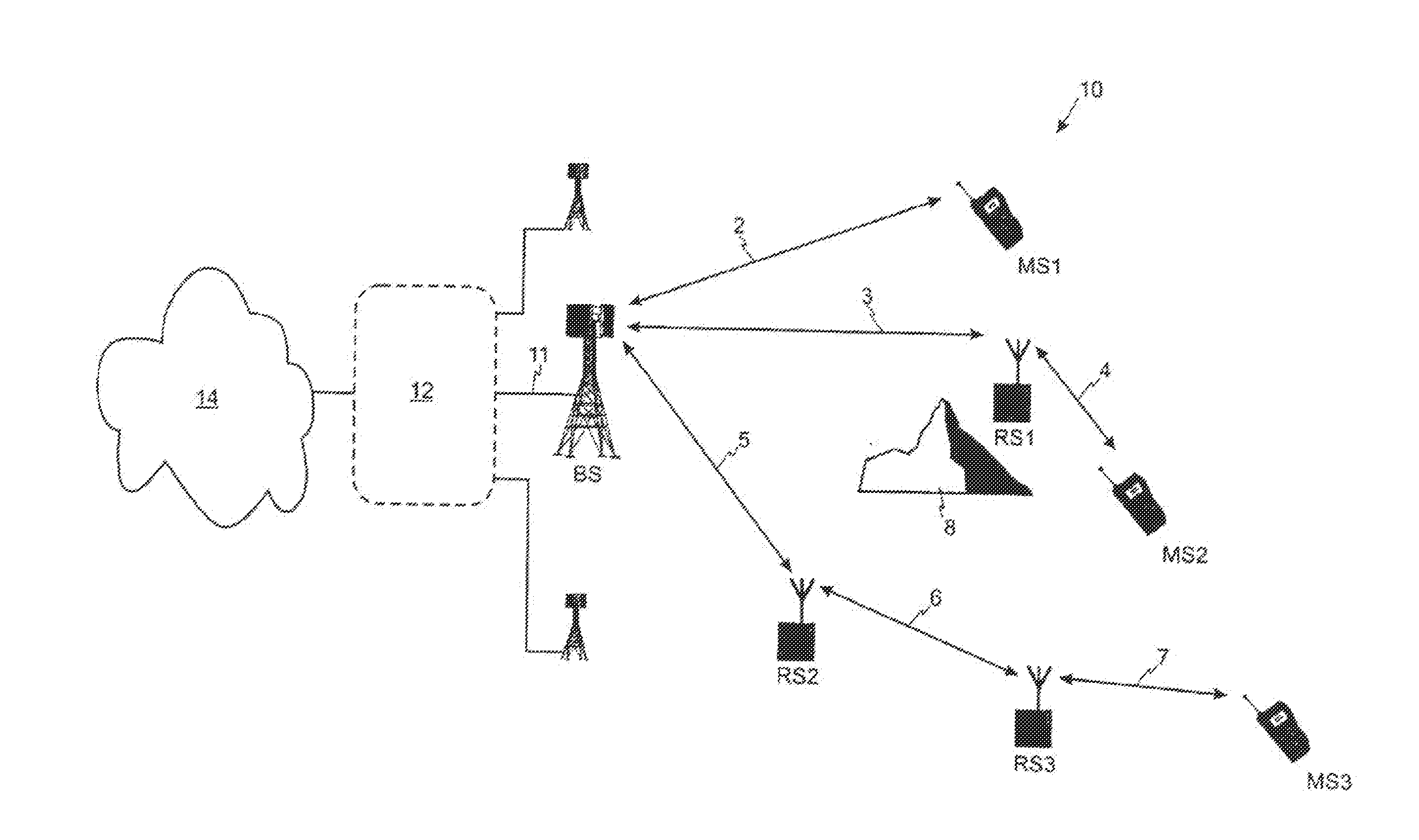
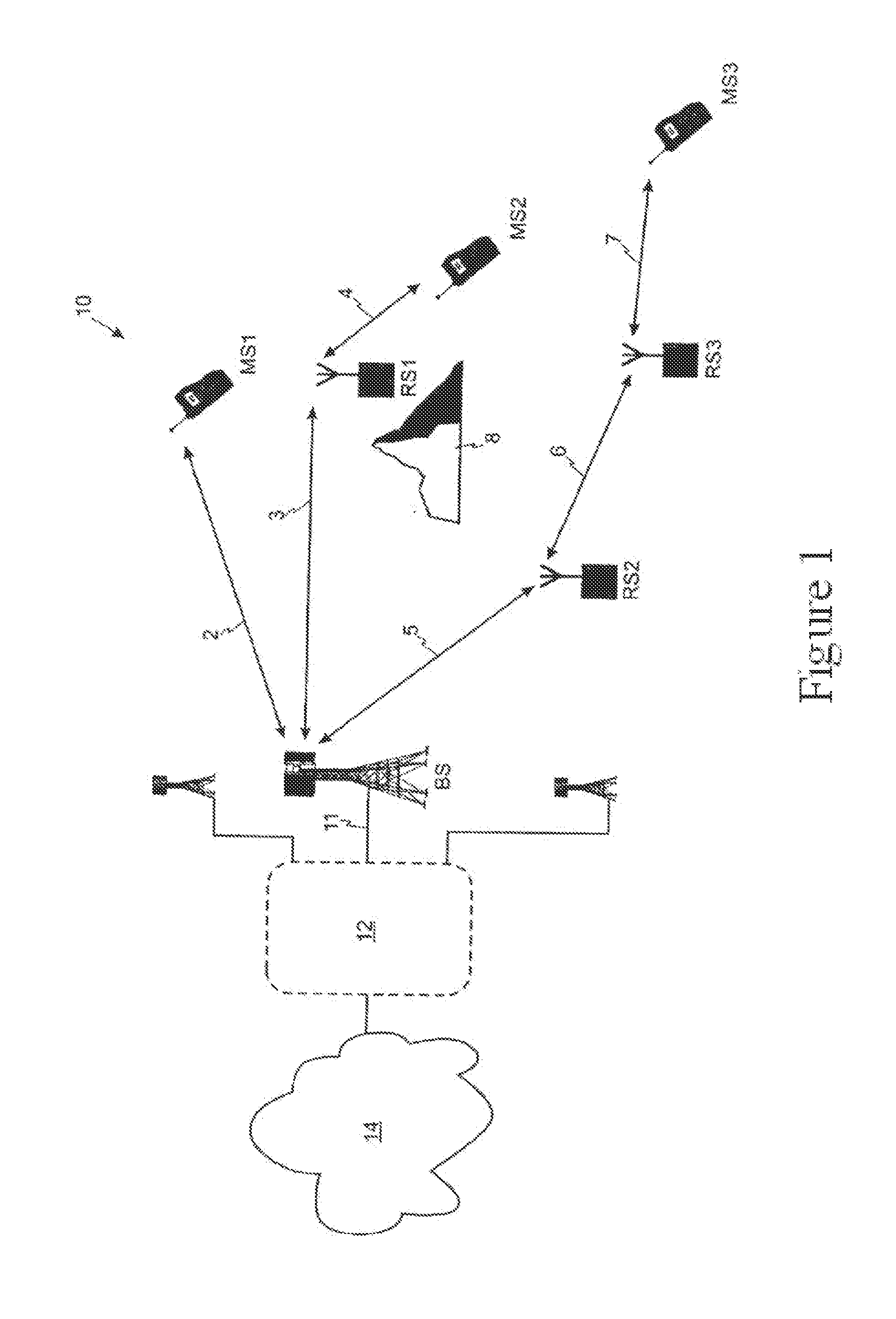
[0046]Embodiments of the invention will be described with reference to a wireless system 10 of the type shown in FIG. 1 in which a base station BS serves a set of terminals MS1-MS3 via direct transmission paths and via multi-hop transmission paths which use relay stations RS1-RS3. FIG. 4 shows a first embodiment of a time-division duplexed transmission frame transmitted by a base station BS which is divided into a downlink sub-frame 20 and an uplink sub-frame 25. As described above, the base station BS, relay stations RS1-RS3 and terminals MS1-MS3 are all synchronized to the time-division duplexed transmission frame.

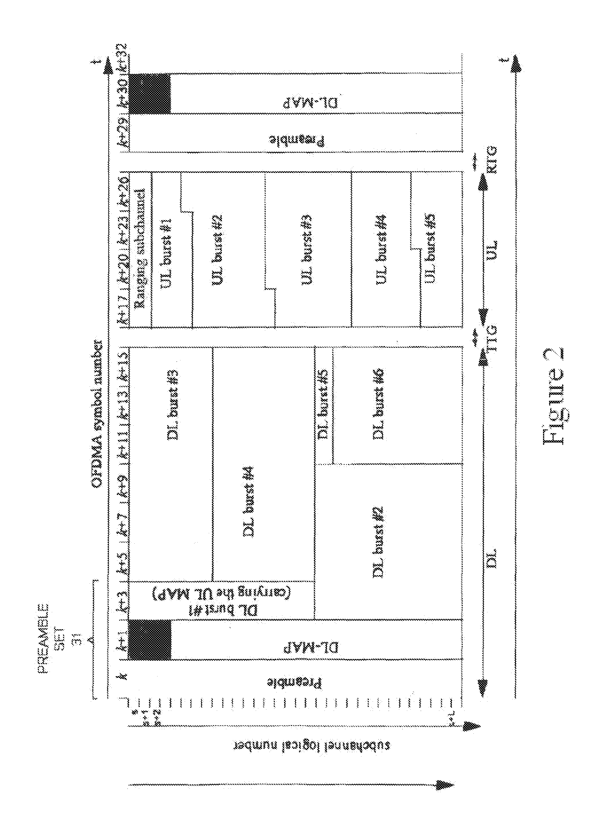
[0047]In this embodiment the downlink sub-frame 20 transmitted by the base station is divided into two parts 30, 40. The first part 30 begins with a first preamble set 31. This first preamble set 31 carries control information which is intended for end terminals (e.g. mobile stations or fixed wireless terminals). As described previously in connection with FIG. 2, the fir...


PUM


Abstract

A wireless network includes a base station which can serve terminals directly, or via multi-hop transmission paths via relay stations. The base station transmits a downlink sub-frame which includes a first set of frame control information and a second set of frame control information. The second set of frame control information occupies a different position within the downlink sub-frame compared to the first set of frame control information. A relay station is able to transmit a downlink sub-frame to a terminal, or another relay station, while still being able to receive a set of frame control at a different time during the downlink sub-frame. The invention is especially useful in a wireless network in which the downlink transmissions of a base station and a relay station are synchronized to one another and where the downlink transmissions of a base station and relay station occupy the same, or similar, frequency bearer.

Description

PRIORITY CLAIM[0001]This application is a continuation of and claims the benefit of priority from U.S. patent application Ser. No. 12 / 447,008, entitled “Frame Structure for a Multi-Hop Wireless System” and filed on Jan. 15, 2010, which is a National Stage of and claims the benefit of priority from International Application No. PCT / EP2007 / 061357, entitled “Frame Structure for a Multi-Hop Wireless System” and filed on Oct. 23, 2007, which claims the benefit of priority from European Patent Application Serial No. 06022383.1, filed on Oct. 26, 2006, all of which are fully incorporated herein by reference for all purposes.BACKGROUND[0002]1. Field of the Application[0003]This invention relates to wireless transmission systems which can support multi-hop transmission paths.[0004]2. Background of the Disclosure[0005]There have been various proposals to create wireless networks to provide Broadband Wireless Access (BWA). These networks can offer an alternative to conventional wired networks ...

Claims


Application Information

Patent Timeline
Patent Type & Authority Applications(United States)
IPC IPC(8): H04L12/741H04B7/14H04L45/74
CPCH04B7/14H04L45/74H04B7/155H04B7/2606H04L5/0016H04L5/0039H04L5/0044H04L5/0053H04L5/1469H04L25/03866H04L27/2656H04L1/0006H04L1/0083H04L5/1415H04W28/02H04L2101/677
Inventor NADEN, JAMESSENARATH, GAMINISTEER, DAVID
Owner APPLE INC
Why Eureka
Try Eureka