Separate type safety injection tank and integral type reactor having the same

a safety injection tank and reactor technology, applied in the direction of nuclear reactors, nuclear elements, greenhouse gas reduction, etc., can solve the problems of reducing the efficiency of safety injection, and drastically losing coolan

Active Publication Date: 2014-02-20
KOREA ATOMIC ENERGY RES INST
View PDF8 Cites 17 Cited by
  • Summary
  • Abstract
  • Description
  • Claims
  • Application Information

AI Technical Summary

Benefits of technology

[0025]According to another embodiment, the integral type reactor may further comprise a check valve installed at the safety injection pipe su

Problems solved by technology

In case of the separate type reactor provided with large pipes, coolant is drastically lost when the large pipes are ruptured.
As a result, a pressure equilibrium state between the reactor and a reactor building cannot be rapidly implemented, and there is a difficulty in performing safety injection by a gravitational head of water.
In the safety injection tank configured to pressurize coolant using gas, if a reference pressure is set to be lower than a reactor pressure predicted i

Method used


Image

  • Separate type safety injection tank and integral type reactor having the same
  • Separate type safety injection tank and integral type reactor having the same
  • Separate type safety injection tank and integral type reactor having the same

Examples


Embodiment Construction

[0042]Description will now be given in detail of the exemplary embodiments, with reference to the accompanying drawings. For the sake of brief description with reference to the drawings, the same or equivalent components will be provided with the same reference numbers, and description thereof will not be repeated. As used herein, the singular forms are intended to include the plural forms as well, unless the context clearly indicates otherwise.

[0043]Hereinafter, a separate type safety injection tank according to the present invention will be explained in more detail with reference to the attached drawings. The suffixes attached to components of the separate type safety injection tank, such as ‘unit’ and ‘system’ were used for facilitation of the detailed description of the present invention. Therefore, the suffixes do not have different meanings from each other.

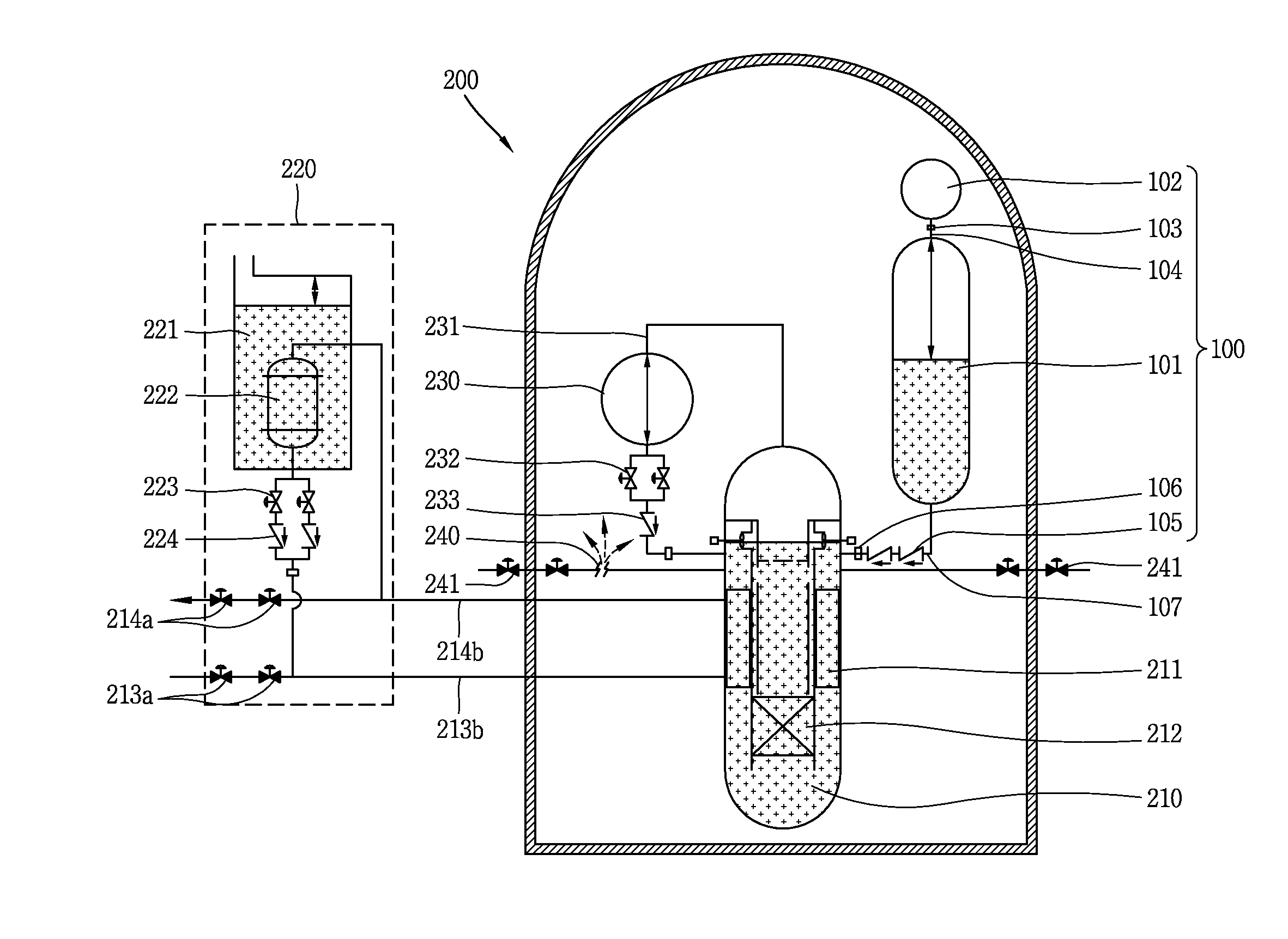
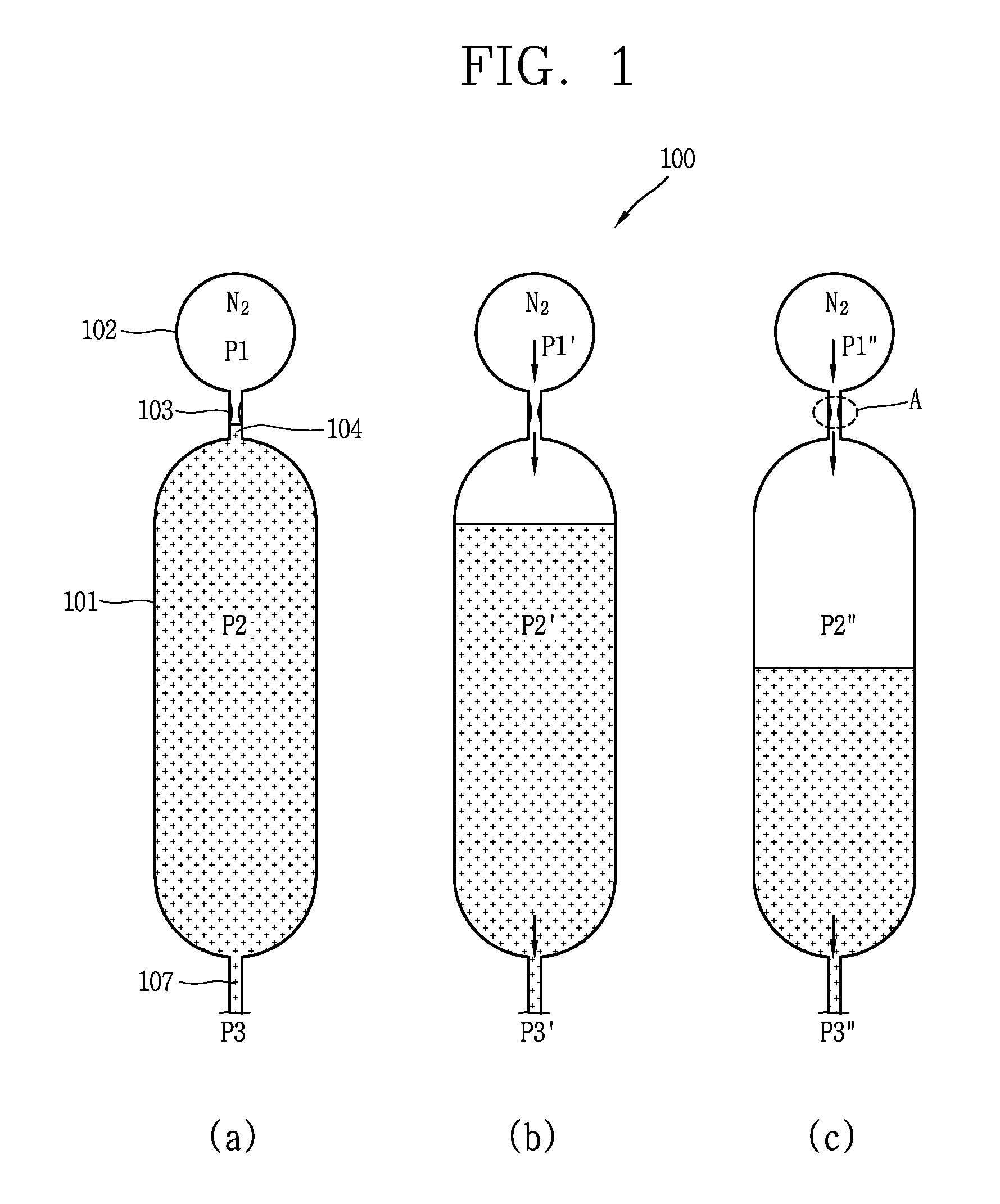
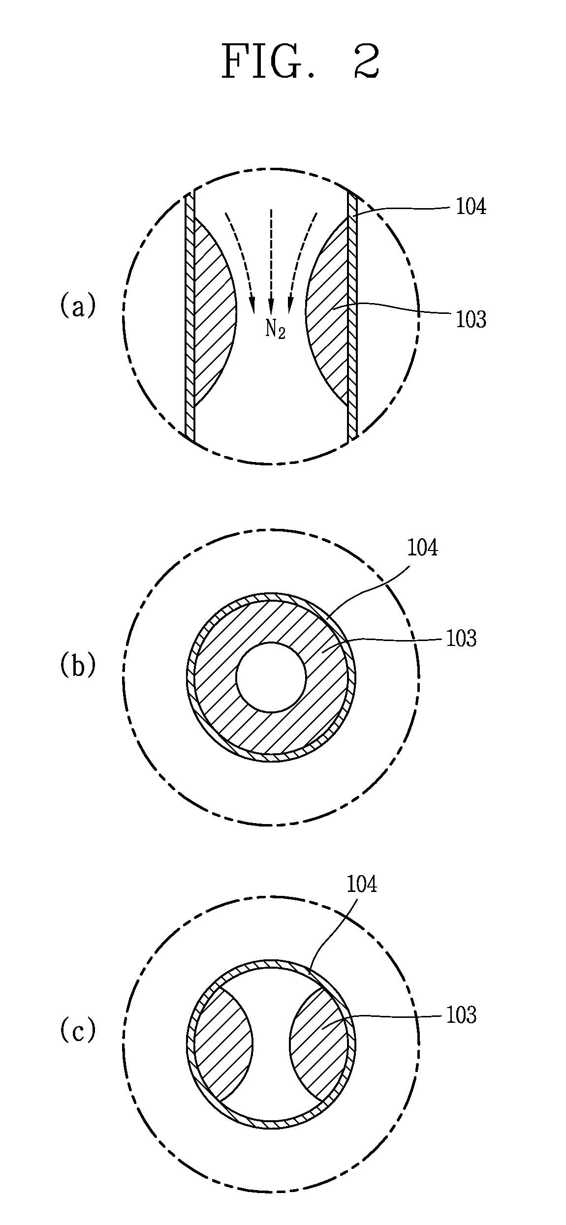
[0044]The passive safety injection systems (core makeup tanks and safety injection tanks) and the passive residual heat re...


PUM


Abstract

A separate type safety injection tank comprises: a coolant injection unit connected to a reactor coolant system by a safety injection pipe such that coolant stored therein is injected into the reactor coolant system by a pressure difference from the reactor coolant system when a loss-of-coolant-accident (LOCA) occurs; a gas injection unit connected to the coolant injection unit, and configured to pressurize the coolant injected into the reactor coolant system, by introducing gas stored therein to an upper part of the coolant injection unit in the loss-of-coolant-accident; and a choking device disposed between the coolant injection unit and the gas injection unit, and configured to contract a flow cross-sectional area of the gas introduced to the coolant injection unit, and configured to maintain a flow velocity and a flow rate of the gas introduced to the coolant injection unit as a critical flow velocity and a critical flow rate when a pressure difference between the coolant injection unit and the gas injection unit is more than a critical value.

Description

CROSS-REFERENCE TO RELATED APPLICATION [0001]Pursuant to 35 U.S.C. §119(a), this application claims the benefit of earlier filing date and right of priority to Korean Application No. 10-2012-0089643, filed on Aug. 16, 2012, the contents of which is incorporated by reference herein in its entirety.BACKGROUND OF THE INVENTION[0002]1. Field of the Invention[0003]The present invention relates to a safety injection system capable of injecting coolant to a reactor coolant system when a loss-of-coolant-accident (LOCA) occurs on an integral type reactor.[0004]2. Background of the Invention[0005]An integral type reactor has a characteristic that large pipes connected with main components such as a core, steam generators, a pressurizer, and pumps are not required, because the main components are installed in a reactor vessel. Pipes configured to connect a chemical and volume control system, a safety injection system, a shutdown cooling system, a safety valve, etc. with the reactor vessel of t...

Claims


Application Information

Patent Timeline
IPC IPC(8): G21C15/18
CPCG21C15/18G21C1/32Y02E30/00Y02E30/30G21C9/00G21D3/04
Inventor KIM, YOUNG INBAE, YOUNG MINYOON, JU HYEONKIM, KEUNG KOO
Owner KOREA ATOMIC ENERGY RES INST
Why Eureka
Try Eureka