Method and apparatus for delivering power using external data

Active Publication Date: 2014-02-20
STEM
View PDF17 Cites 21 Cited by
  • Summary
  • Abstract
  • Description
  • Claims
  • Application Information

AI Technical Summary

Benefits of technology

[0010]Embodiments of the present invention include control methods employed in distributed energy storage systems that are located behind utility meters typically located at, but not limited to, medium and large commercial and industrial locations. According to such control methods, these distributed energy storage systems operate semi-autonomously, but may be in frequent contact with a cloud-based optimization engine that is configured to develop energy control solutions based on various data inputs and to communicate these energy control solutions to one or more of the distributed energy storage systems. One of the goals of

Problems solved by technology

The cost to a utility for generating or purchasing electrical energy increases dramatically during periods of peak use versus periods of off-peak usage.
The higher rates charged during peak usage periods can lead to significantly higher energy costs for the user, especially when the user's period(s) of high demand coincides with or falls within the interval set by the utility as peak hours.
Energy storage mediums, especially battery energy storage, are expensive and, while various techniques are known by which an energy storage system can be used to optimize energy use at a business or home, such techniques are generally inefficient in applying stored energy to effectively control the energy use at an electric load location.
Consequently, an impractical quantity of energy storage mediums are required at an electric load location to rea

Method used


Image

  • Method and apparatus for delivering power using external data
  • Method and apparatus for delivering power using external data
  • Method and apparatus for delivering power using external data

Examples


Example

[0058]To facilitate understanding, identical reference numerals have been used, where possible, to designate identical elements that are common to the figures. It is contemplated that elements disclosed in one embodiment may be beneficially utilized on other embodiments without specific recitation. The drawings referred to here should not be understood as being drawn to scale unless specifically noted. Also, the drawings are often simplified and details or components omitted for clarity of presentation and explanation. The drawings and discussion serve to explain principles discussed below, where like designations denote like elements.

DETAILED DESCRIPTION

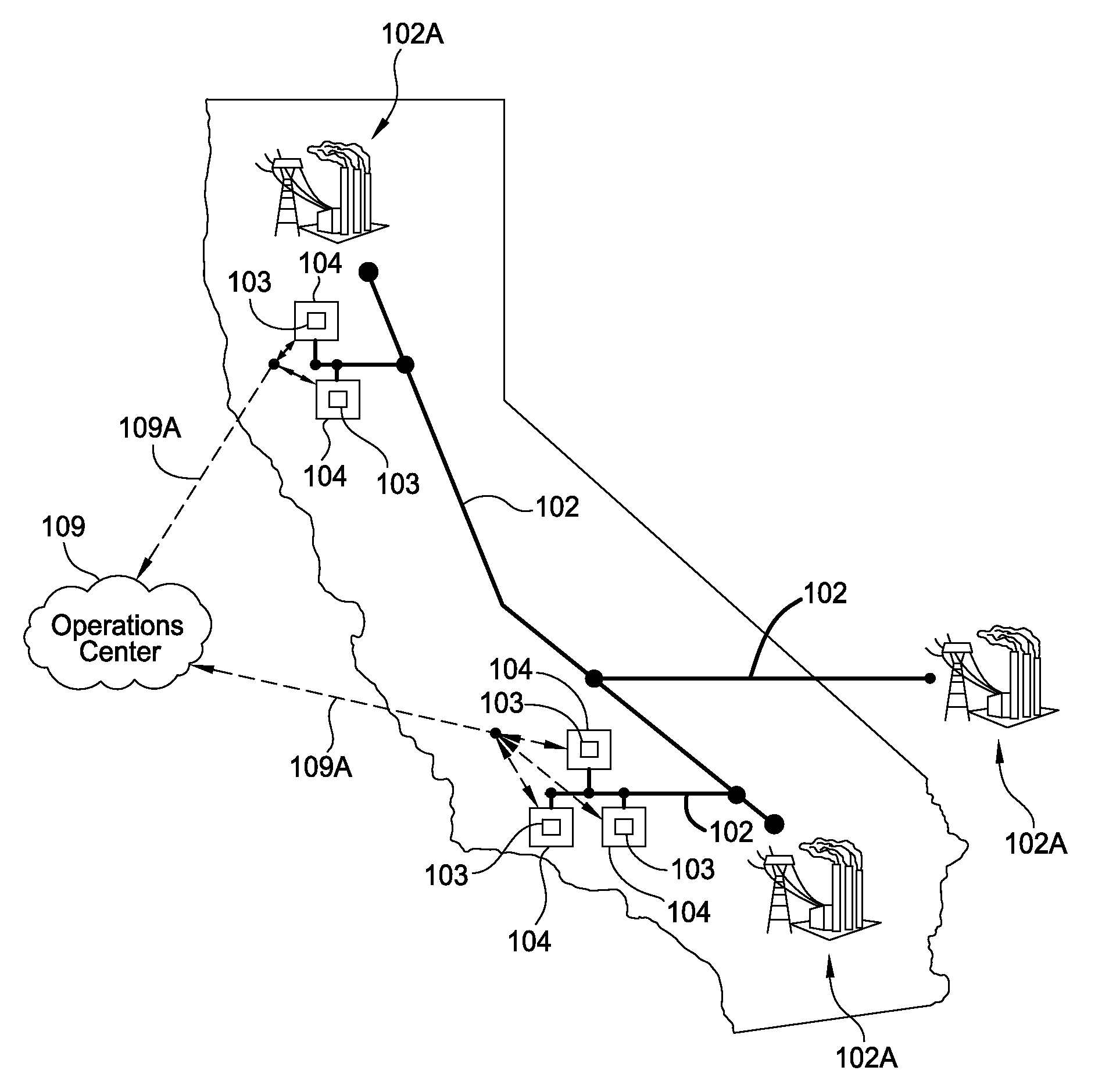
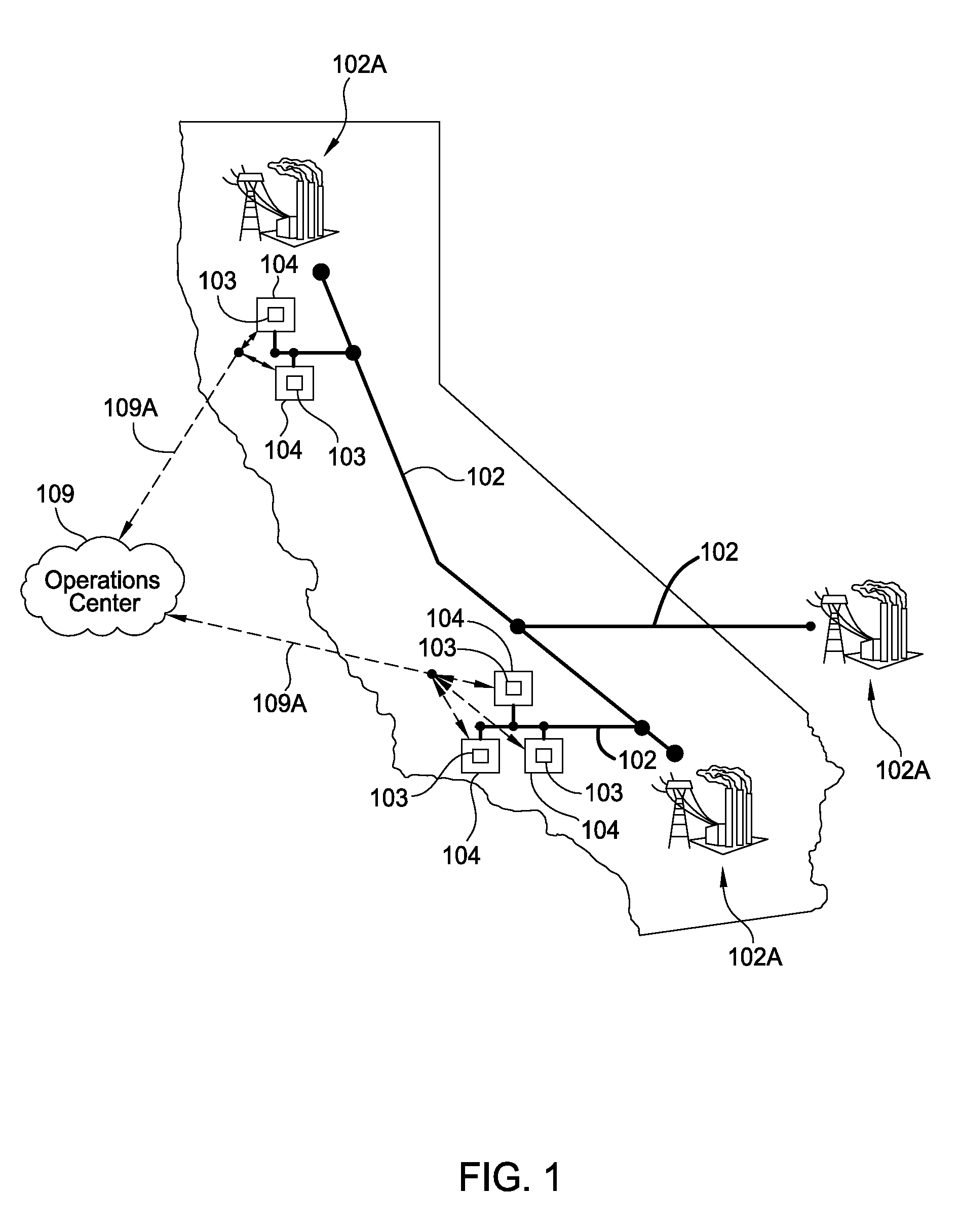
[0059]Embodiments of the present invention relate to distributed energy storage systems installed either behind a utility's electric meter at electric load locations, such as commercial electric load locations, residential sites and / or commercial solar / wind production sites. The term commercial electric load location as used herein,...


PUM


Abstract

A control system for an energy storage system located behind a utility meter uses a unique, feedback-based, communication and control method to reliably and efficiently maximize economic return of the energy storage system. Operating parameters for the energy storage system are calculated at an external, centralized data center, and are selected to prevent electrical power demand of an electric load location from exceeding a specified set-point by discharging energy storage devices, such as DC batteries, through a bidirectional energy converter during peak demand events. The control system can operate autonomously in the case of a communications failure.

Description

CROSS-REFERENCE TO RELATED APPLICATIONS[0001]This application is a continuation of co-pending U.S. patent application Ser. No. 13 / 967,256, filed Aug. 14, 2013 [Atty. Dkt No. STEM / 0016US], which claims benefit of U.S. Provisional Patent Application Ser. No. 61 / 683,113, filed Aug. 14, 2012 [Atty. Dkt No. STEM / 0008L], U.S. Provisional Patent Application Ser. No. 61 / 693,684, filed Aug. 27, 2012 [Atty. Dkt No. STEM / 0009L] and U.S. Provisional Patent Application Ser. No. 61 / 801,274, filed Mar. 15, 2013 [Atty. Dkt No. STEM / 0016L], which are all herein incorporated by reference.BACKGROUND OF THE INVENTION[0002]1. Field of the Invention[0003]Embodiments of the present invention generally relate to a method and an apparatus for controlling fluctuations in power and amount of power used at an electric load location and / or on an electrical grid.[0004]2. Description of the Related Art[0005]Energy demand at a commercial site, such as a business, or at home will vary over the time of day. In a typ...

Claims


Application Information

Patent Timeline
IPC IPC(8): H02J4/00
CPCH02J4/00H02J3/32Y04S10/14G05F1/66G06Q50/06H02J13/00034Y02E40/70Y02E60/00Y02P80/10Y04S10/50H02J13/00002Y04S10/30H02J3/00H02J3/003G05B13/026G05B2219/39361H02J13/00
Inventor KEARNS, BENBURLINSON, JONSTEVENS, DREW
Owner STEM
Why Eureka
Try Eureka