
Mobilized laundry service system

a technology of laundry service and mobile devices, applied in forecasting, instruments, data processing applications, etc., can solve the problems of unhappy customers, bar staff cannot be moved/handled automatically, and the bar lacks the means of restraining the laundry, etc., to achieve efficient vehicle routing

Inactive Publication Date: 2014-02-20
LEE SUNG OK +1
View PDF5 Cites 14 Cited by
  • Summary
  • Abstract
  • Description
  • Claims
  • Application Information

AI Technical Summary

Benefits of technology

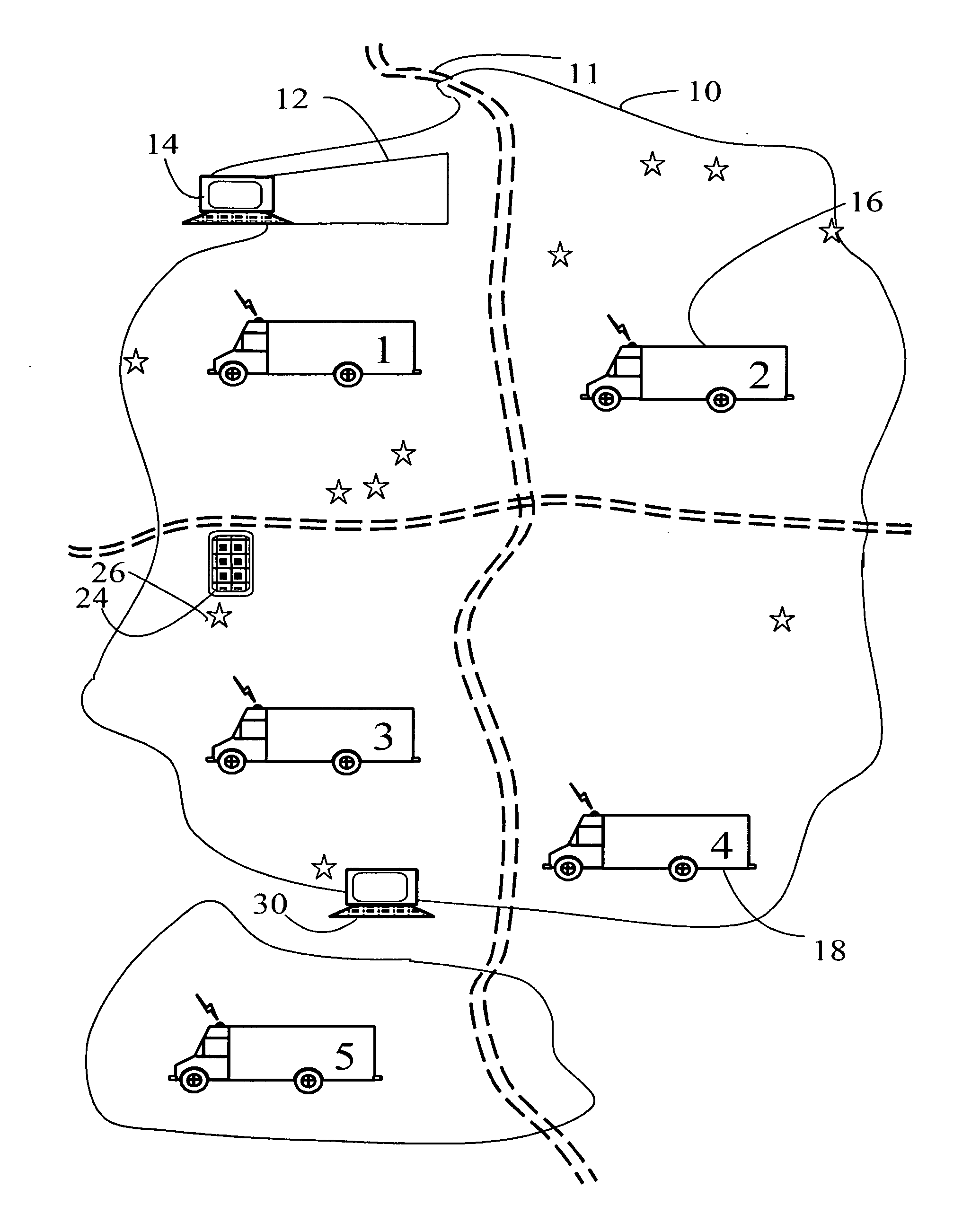
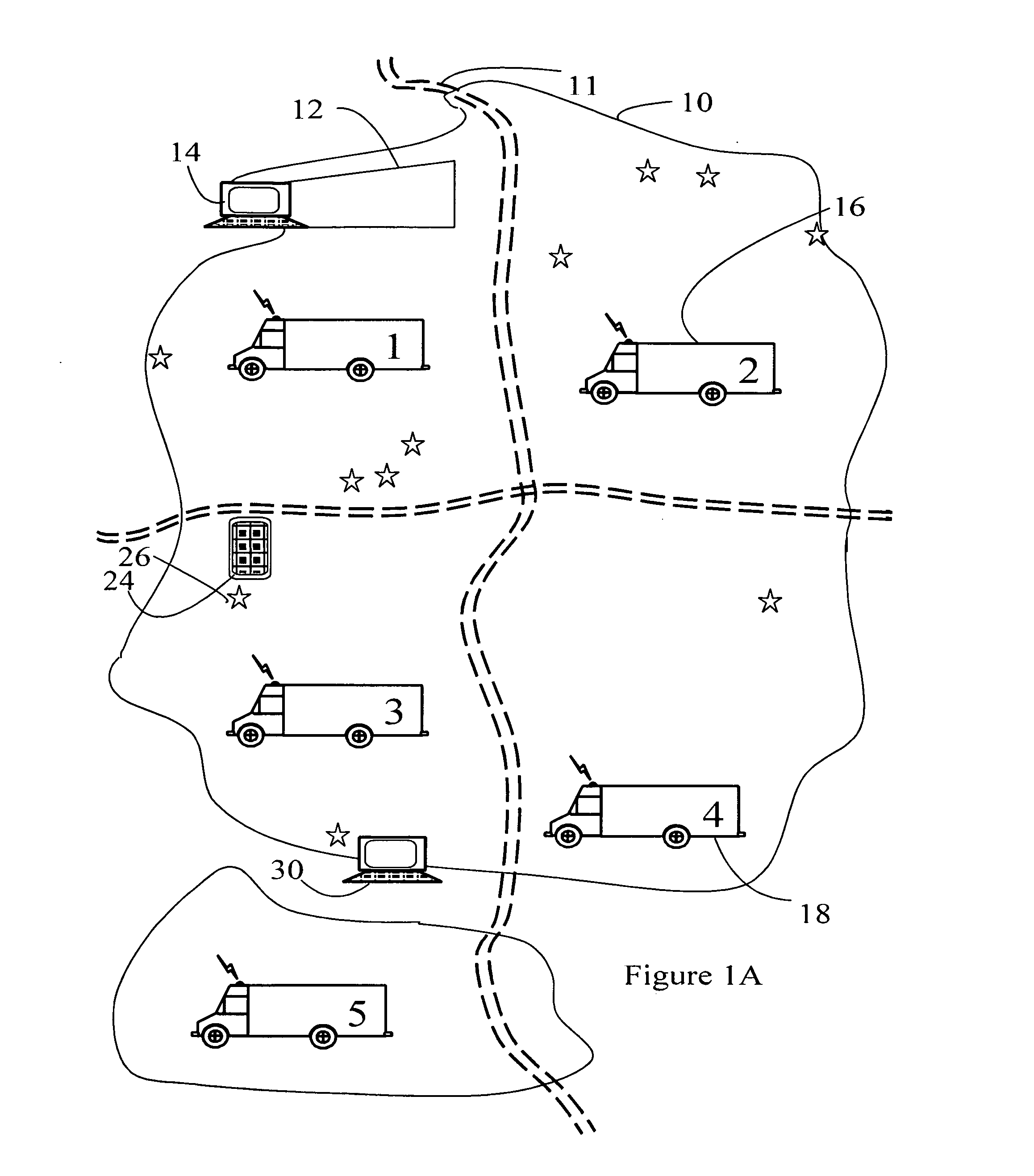
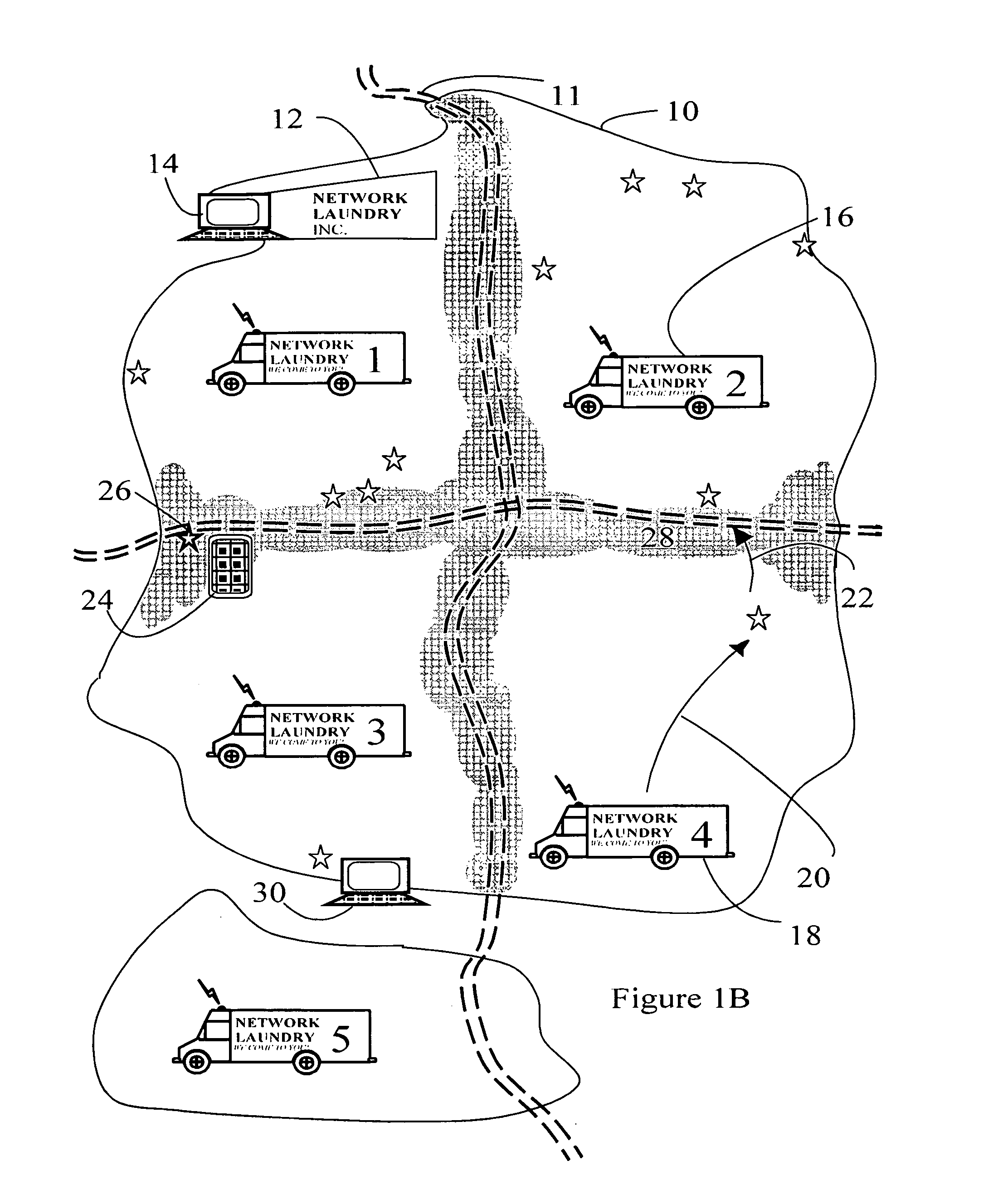
The present invention is a specialized laundry vehicle that goes beyond the traditional services of laundry. It helps customers pick up their laundry from their homes, offices, or any other location that is convenient for them. The vehicle has an in-truck hanging conveyor that allows for efficient handling of laundry, keeping it clean and organized during transport. It also has a pickup / scheduling / routing module that helps route the vehicle to different customer locations efficiently. Overall, this invention provides a flexible and efficient solution to meet customers' laundry needs.

Problems solved by technology

Secondly the truck of the '077 patent operates on a regular and fixed schedule, for example fixed laundry return times when customers can find the truck parked in its regular location.
Chaos and unhappy customers would result if the truck were absent from these fixed locations at times customers believed they could pick up their laundry.
Such bars lack means of restraining the laundry from sliding along the bar during truck motions.
Such bars also lack means of moving / handling the laundry automatically.

Method used


Image

  • Mobilized laundry service system
  • Mobilized laundry service system
  • Mobilized laundry service system

Examples


first embodiment

[0231]FIG. 7 shows the truck-mounted hanging conveyor of the system. Ceiling 702 holds support 704 which in turn holds rail 706. Note that in practice, such systems often have the rail 706 held on the bottom by support 704, rather than the top. The top of the rail is usually the part that moves, though this is not mandatory and depends on the details of the hanger conveyor. Hanger carrier 708 (also called a hanger “truck” but NOT meaning a vehicle, just a part of the conveyor system) is an optional feature of such systems, usually each hanger carrier 708 will have a plurality of individual hanger apertures 710 separated and defined by hanger aperture blocks 712. Obviously, part of the rail and carriers move while the supports remain still stationary in most systems, though there are variations.

second embodiment

[0232]Note that the support of the system by the ceiling of the vehicle may by itself be sufficient to distinguish the system over laundry vehicles which simply have bars running from one wall of the cargo vehicle to another wall. However, FIG. 8 shows the truck-mounted conveyor of the system. Wall 802 supports wall mount 804 which in turn supports rail 806.

[0233]Hanger aperture 808 and hanger aperture block 810 are much as described previously, however in this case the moving apertures are within the rail and no hanger carrier is employed.

[0234]FIGS. 9A and 9B show simply alternative embodiments of the truck-mounted conveyor of the system, in which the rail has thereon various shapes of hanger slot blocks (bumps) and hanger slots: square, saw-toothed (triangular) and so on.

[0235]FIG. 10 shows a second exemplary embodiment of the truck-mounted conveyor of the system. Rail 1002 is held in place by support 1004, as previously discussed.

[0236]In this exemplary embodiment a hanger compa...


PUM


Abstract

A distributed laundry system having mobilized laundry vehicles, including true laundry conveyors in the vehicles, and including a specialized distributed computer network in the vehicles to handle the circumstances of mobile laundry operations, such as special laundry instructions. In addition, procedures and operations which allow the vehicles to cooperate to provide efficient pickup and drop off services at locations of the customers' choices (such as at home or work), including flexible territories for the trucks, customer user interfaces on mobile devices such as cell phones, mobile computing devices and the like, and precise time estimates of pick-up and drop-off times.

Description

COPYRIGHT NOTICE[0001]A portion of the disclosure of this patent document contains material which is subject to copyright protection. The copyright owner has no objection to the facsimile reproduction by anyone of the patent document or the patent disclosure, as it appears in the Patent and Trademark Office patent file or records, but otherwise reserves all copyright rights whatsoever. 37 CFR 1.71(d).CROSS-REFERENCE TO RELATED APPLICATIONS[0002]N / AFIELD OF THE INVENTION[0003]This invention relates generally to laundry service devices and systems, and specifically to an improved laundry system distributed across a number of vehicles, computers and mobile devices.STATEMENT REGARDING FEDERALLY FUNDED RESEARCH[0004]This invention was not made under contract with an agency of the US Government, nor by any agency of the US Government.BACKGROUND OF THE INVENTION[0005]Laundry service generally is provided by means of a single system: one or more fixed drop off and pickup locations (dry clea...

Claims


Application Information

Patent Timeline
IPC IPC(8): G06Q10/08G06Q50/10
CPCG06Q10/04G06Q10/047G06Q50/10
Inventor LEE, SUNGLEE, CHANG SHIN
Owner LEE SUNG OK
Learn More