Check patentability & draft patents in minutes with Patsnap Eureka AI!

Electronic control and display unit

Inactive Publication Date: 2014-02-20
CLAAS SELBSTFAHRENDE ERNTEMASCHINEN GMBH
View PDF12 Cites 28 Cited by
  • Summary
  • Abstract
  • Description
  • Claims
  • Application Information

AI Technical Summary

Benefits of technology

The present invention provides a visualization device that only visualizes relevant parameters and allows for easy change of vehicle parameters. The device features icons representing parameter settings and virtual adjusting elements, such as rotary and sliding switches, that can be easily activated to change the parameter. The virtual rotary switch provides a large amount of information and is highly transparent to the operator. The display can be subdivided into visualization regions within a navigation level, which ensures that only context-relevant parameters are ever visualized and the visualization according to a repeating pattern results in the rapid orientation of the operator. Overall, the device allows for efficient and quick learning and easy selection of parameters.

Problems solved by technology

Such known systems have the primary disadvantage, however, that a plurality of information is visualized directly on the screen even if the information does not need to be monitored or edited at the time.
This large amount of information can result in the overstimulation of an operator of the machine since a considerable amount of information is always accessible and because the operator must handle the priorization by his or herself.
That is, the operator is compelled to distinguish important information from less important information, which requires time and effort.
In addition, it is difficult to orient one's self to a display structured in this manner since the screen structure constantly changes.
Although a visualization device structured in such a way ensures better orientation on the screen, the deice or system is disadvantageous in that the large amount of visualized information may not be required for the process currently underway resulting in unnecessary overstimulation of the driver operating the particular agricultural working machine when confronted with the visualized information.

Method used


Image

  • Electronic control and display unit
  • Electronic control and display unit
  • Electronic control and display unit

Examples


Embodiment Construction

[0024]The following is a detailed description of example embodiments of the invention depicted in the accompanying drawings. The example embodiments are presented in such detail as to clearly communicate the invention and are designed to make such embodiments obvious to a person of ordinary skill in the art. However, the amount of detail offered is not intended to limit the anticipated variations of embodiments; on the contrary, the intention is to cover all modifications, equivalents, and alternatives falling within the spirit and scope of the present invention, as defined by the appended claims.

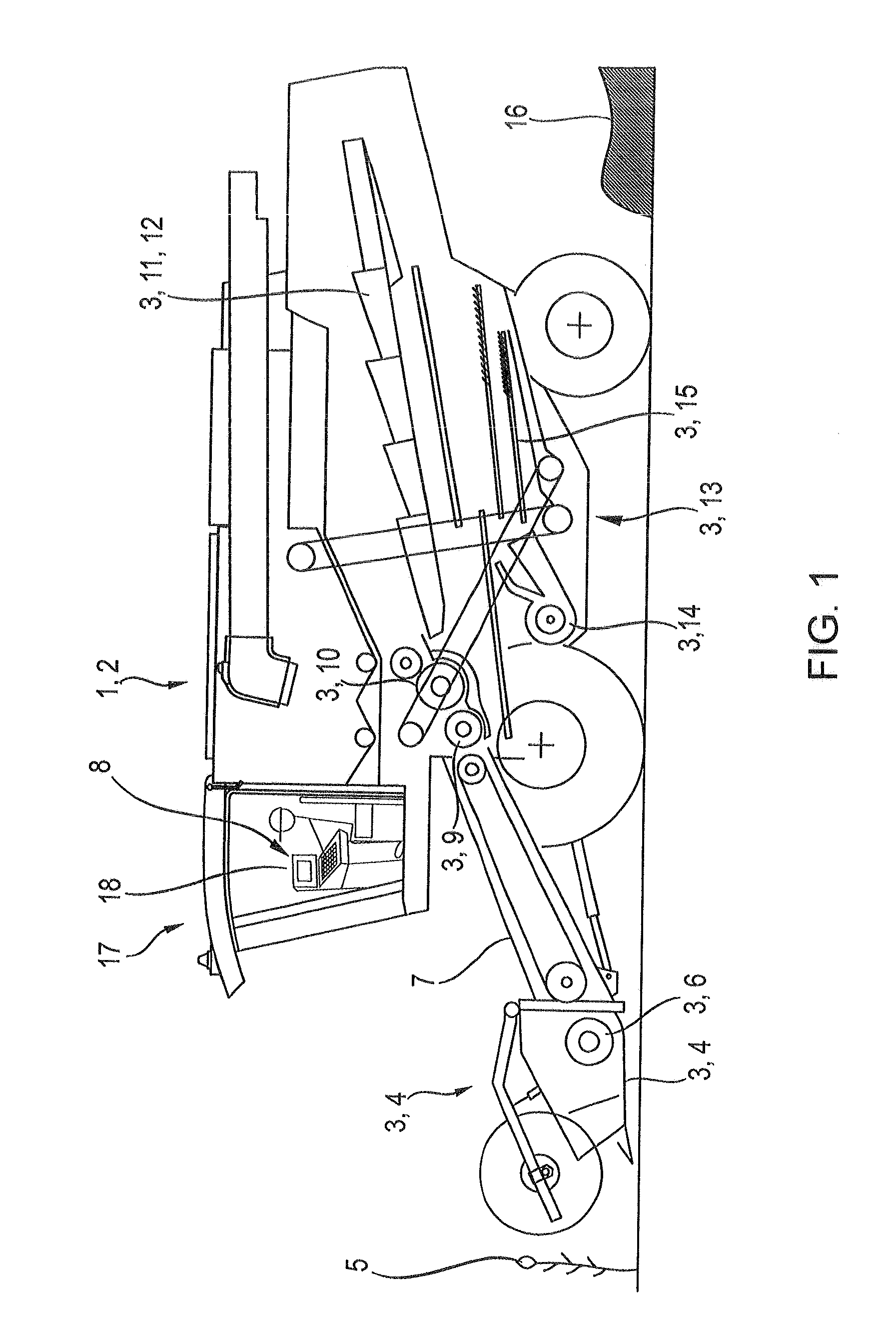
[0025]FIG. 1 depicts an agricultural working machine 1 configured as a combine harvester 2 and the working units 3 thereof. The combine harvester 2 accommodates a header 4 in the front region thereof. The header 4 picks up crop 5, cuts the crop and transfers the crop via a feed device 6 to the downstream feed rake 7. Via the feed rake 7, the crop 5 is transferred in a manner known per se to...


PUM


Abstract

An electronic control and display unit comprises a display and at least one control unit. The display has a plurality of visualization regions and icons representing settings of parameters are assigned to the display in one or more visualization regions. A particular icon represents a parameter of a working machine. Activating the particular icon causes at least one virtual adjusting element to be shown on the display. The virtual adjusting element can be edited in order to change the parameter of the working machine.

Description

CROSS-REFERENCE TO A RELATED APPLICATION[0001]The invention described and claimed hereinbelow is also described in German Patent Application DE 10 2012 107551.4, filed on Aug. 17, 2012. The German Patent Application, subject matter of which is incorporated herein by reference, provides the basis for a claim of priority of invention under 35 U.S.C. 119(a)-(d).BACKGROUND OF THE INVENTION[0002]The invention relates to an electronic control and display unit including a display having a plurality of visualization regions, wherein icons representing the parameter settings are assigned to one or more of the visualization regions.[0003]Various display devices are known that are used to visualize and edit processes, e.g., on mobile agricultural working machines. Document DE 102 03 370, for example, discloses a method for controlling a user interface, in which an interactive user interface permits the visualization of a plurality of control windows. In addition to the overlapping depiction of...

Claims


Application Information

Patent Timeline
IPC IPC(8): G06F3/0481
CPCG06F3/04817G06F2203/04803G06F3/04883G06F3/04886G06F3/04847A01D41/127A01D41/1274
Inventor GREVINGA, MARKUSLOSCH, MICHAEL
Owner CLAAS SELBSTFAHRENDE ERNTEMASCHINEN GMBH
Features
  • R&D
  • Intellectual Property
  • Life Sciences
  • Materials
  • Tech Scout
  • Unparalleled Data Quality
  • Higher Quality Content
  • 60% Fewer Hallucinations
Learn More