Head-mounted display

a display and display technology, applied in the field of head-mounted displays, can solve the problems of user hands and inconvenient use for users

Active Publication Date: 2014-02-27
SHARP KK
View PDF2 Cites 55 Cited by
  • Summary
  • Abstract
  • Description
  • Claims
  • Application Information

AI Technical Summary

Benefits of technology

[0038]As described above, a head-mounted display of the present invention includes: a mounting section for the user to mount on his/her head, the mounting section including an infrared light irradiation section that irradiates the object to be detected with a predetermined pattern of infrared light and an infrared light detection section that detects the infrared light reflected by the object to be detected, the infrared light irradiation section and the infrared light detection section being placed at a predetermined distance from each other; and a control section including a computing section that computes the three-dimensional coordinates, the computing section computing, from a predetermined pattern of reflection from the object to be detected as obtained by the infrared light detection section, coordinate values of the object to be detected as measured along lines parallel to f...

Problems solved by technology

This has caused such inconveniences to the user 91 that the product weight of the portable terminal 90 makes the hands of ...

Method used


Image

  • Head-mounted display
  • Head-mounted display
  • Head-mounted display

Examples


embodiment 1

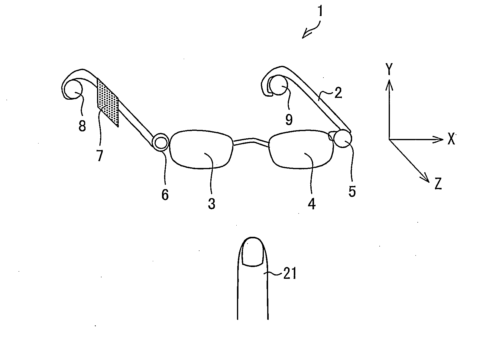
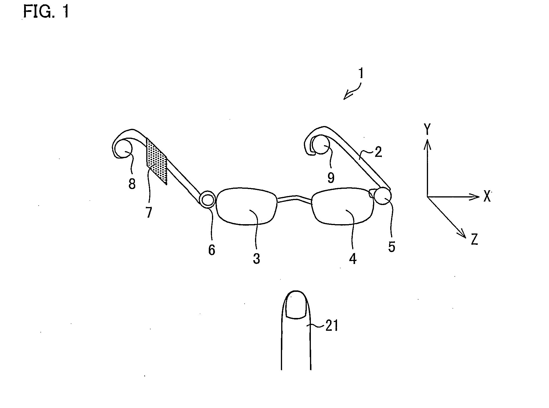
[0065]FIG. 1 is a diagram schematically showing a configuration of a head-mounted display 1 (HMD).

[0066]As shown in FIG. 1, the head-mounted display 1 includes a mounting section 2, a right-eye image display section 3, and a right-eye image display section 4. The mounting section 2 is in the shape of an eyeglass frame so that a user can mount the head-mounted display 1 on his / her head, and the right-eye and left-eye image display sections 3 and 4 serve as a display section that allows the user to view an image.

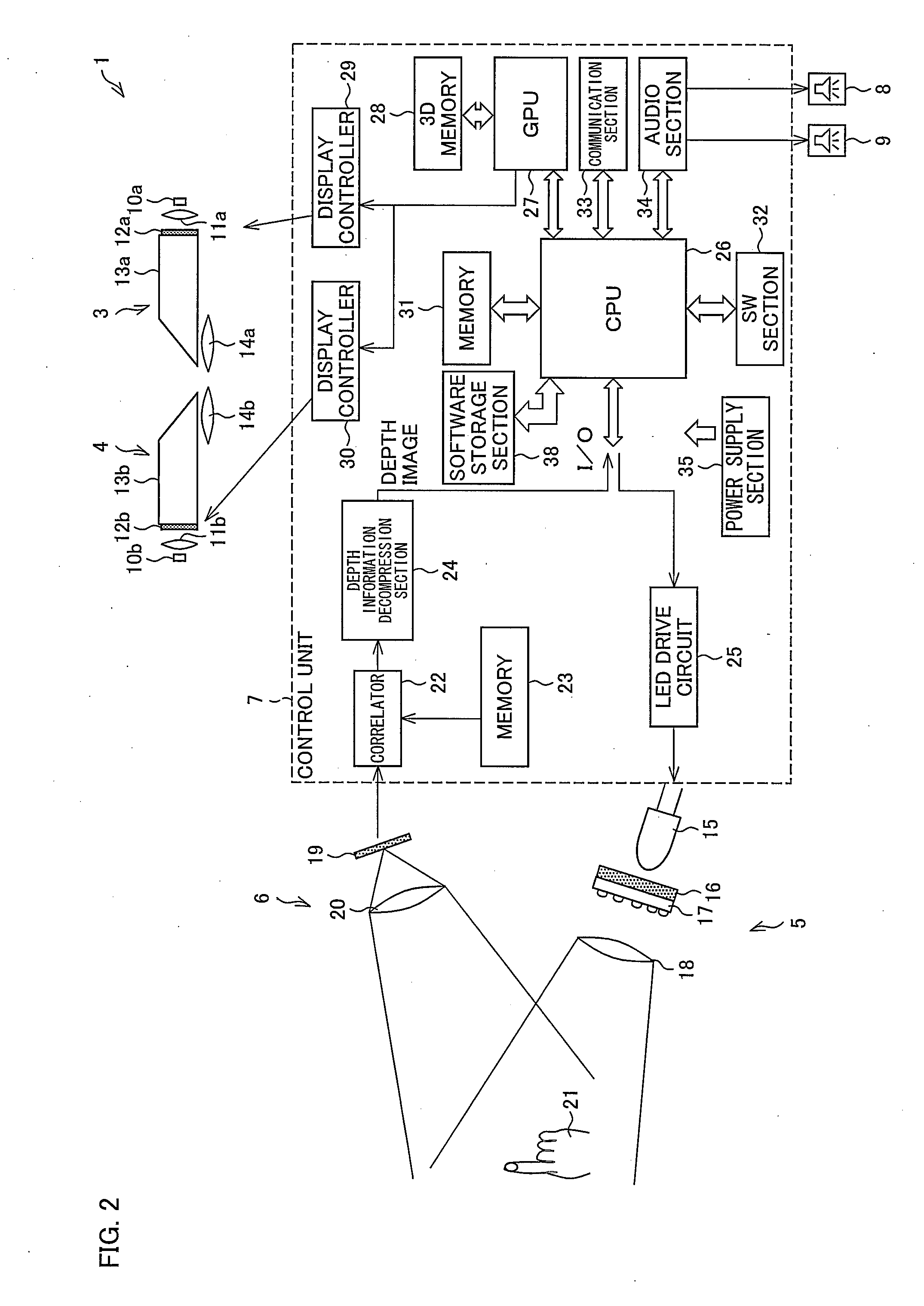
[0067]Moreover, the mounting section 2 is provided with an infrared light irradiation section 5 and an infrared light detection section 6. The infrared light irradiation section 5 irradiates an object to be detected 21 with a predetermined pattern of infrared light, and the infrared light detection section 6 detects the infrared light reflected by the object to be detected 21. The infrared light irradiation section 5 and the infrared light detection section 6 are placed at a p...

embodiment 2

[0156]A second embodiment of the present invention is described below with reference to FIGS. 11 through 20. A head-mounted display 1a of the present embodiment differs from Embodiment 1 in that in order to further improve a sense of reality, the head-mounted display 1a includes a right-eye imaging device 36 and a left-eye imaging device 37 for capturing a background image as a color image, and the other components of the head-mounted display 1a are the same as those described in Embodiment 1. For convenience of explanation, members having the same functions as those shown in the drawings of Embodiment 1 are given the same reference signs, and as such, are not described below.

[0157]FIG. 11 is a diagram schematically showing a configuration of the head-mounted display 1 including the right-eye imaging device 36 (color camera) and the left-eye imaging device 37 (color camera).

[0158]As shown in FIG. 11, the right-eye imaging device 36 and the left-eye imaging device 37 are provided in ...


PUM


Abstract

A mounting section (2) for a user to mount on his/her head includes an infrared light irradiation section (5) that irradiates an object to be detected (21) with a predetermined pattern of infrared light and an infrared light detection section (6) that detects the infrared light reflected by the object to be detected (21). The infrared light irradiation section (5) and the infrared light detection section (6) are placed at a predetermined distance from each other. The three-dimensional coordinates of the object to be detected (21) are computed from a predetermined pattern of reflection from the object to be detected (21) as obtained by the infrared light detection section (6).

Description

TECHNICAL FIELD[0001]The present invention relates to a head-mounted display capable of computing the three-dimensional coordinates of an object to be detected.BACKGROUND ART[0002]In recent years, all sorts of information have been computerized along with the evolution of the Internet, and it has become common, for example, to view electronic books, various types of computerized information, etc. via portable terminals such as electronic book players and smartphones.[0003]A portable terminal such as an electronic book player or a smartphone may be placed on a table for use, but may also be often used, for example, by a user lying in a comfortable position.[0004]In such a case as that shown in FIG. 21 where a portable terminal 90 such as an electronic book player or a smartphone is used by a user lying in a comfortable position, the user finds himself / herself having to hold the portable terminal 90 with one hand. Moreover, in performing a predetermined input operation on the portable...

Claims


Application Information

Patent Timeline
IPC IPC(8): G06F3/01
CPCG06F3/011G06F3/012G06F3/017G02B27/017G02B2027/0178G02B2027/0187G02B2027/0138G02B2027/014H04N13/214H04N13/254H04N13/344
Inventor TAKAHAMA, KENGO
Owner SHARP KK
Why Eureka
Try Eureka