Thermally assisted magnetic head, head gimbal assembly, and hard disk drive

a magnetic head and head gimbal technology, applied in the field of magnetic head and head gimbal assembly, can solve the problems of difficult to intensively heat only a desired point, and achieve the effects of reducing the occurrence of writing failure due to insufficient heating, reducing the occurrence of “side erase” and intensive hea

Active Publication Date: 2011-12-13
TDK CORPARATION
View PDF31 Cites 45 Cited by
  • Summary
  • Abstract
  • Description
  • Claims
  • Application Information

AI Technical Summary

Benefits of technology

[0012]According to the present invention, the emitted light from the light emitting element reaches the near-field light generator and thus the near-field light is generated from the near-field light generator. Since the near-field light generator is located adjacent to the magnetic recording element in the medium-facing surface, the temperature increases in a recording region of the magnetic recording medium facing the medium-facing surface, to temporarily lower the coercive force of the recording region. The magnetic recording element is energized during this period of the lowered coercive force to generate a writing magnetic field, whereby information can be written in the recording region.
[0023]Since the present invention enables the suppression of emission of near-field light from the part other than the cusp portion of the near-field light generator, a desired portion of the medium can be selectively heated, whereby high-density recording can be readily implemented by thermally assisted magnetic recording.

Problems solved by technology

When the near-field light is also radiated from the part other than the tip in this manner, it can be difficult to intensively heat only a desired point.
Since this also decreases the coercive force of the track part adjacent to the track where writing is implemented in the recording medium, there could arise the problem of so-called “side erase” which is writing or erasure on the adjacent track.

Method used


Image

  • Thermally assisted magnetic head, head gimbal assembly, and hard disk drive
  • Thermally assisted magnetic head, head gimbal assembly, and hard disk drive
  • Thermally assisted magnetic head, head gimbal assembly, and hard disk drive

Examples


example 1 (fig.18)

Example 1 (FIG. 18): Cusp Portion (Ag) / Base Portion (Al)

example 2 (fig.19)

Example 2 (FIG. 19): Cusp Portion (Au) / Base Portion (Ru)

example 3 (fig.23)

Example 3 (FIG. 23): Cusp Portion (Au) / Base Portion (Pt)

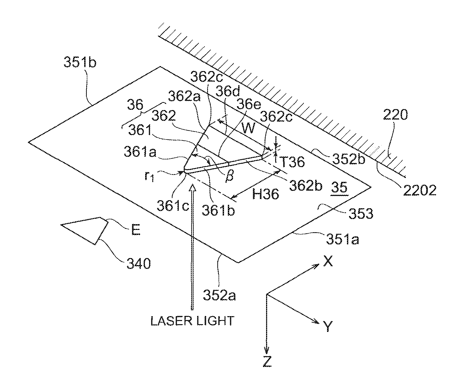
[0204]The dimensions of the near-field light generator in the examples were the length H36 (=90 nm) / maximum width W (=117 nm) / thickness T36 (=30 nm) and the length in the direction H36 of each material was 40 nm for the cusp portion and 50 nm for the base portion. (Reference is made to FIG. 8). Comparative Example 1 was an example in which the entire near-field light generator was made of a single material alone, Comparative Example 2 was an example in which the materials were reverse to those in Example 2, and in either case the entire dimensions were the same as in each example. Comparative Example 3 was an example in which the near-field light generator was comprised of only the cusp portion and the length H36 thereof was 40 nm.

[0205]FIGS. 18 and 19 are intensity distribution diagrams of near-field light in Example 1 and in Example 2, respectively.

[0206]These near-field light generators are comprised of the cusp portion in t...


PUM

PropertyMeasurementUnit
thicknessaaaaaaaaaa
thicknessaaaaaaaaaa
thickaaaaaaaaaa

Abstract

A thermally assisted magnetic head has a medium-facing surface facing a magnetic recording medium; a near-field light generator disposed on a light exit face in the medium-facing surface; a magnetic recording element located adjacent to the near-field light generator; and a light emitting element disposed so that emitted light thereof reaches the near-field light generator; the near-field light generator is comprised of a cusp portion and a base portion; when λin represents a wavelength of the emitted light from the light emitting element immediately before the emitted light reaches the near-field light generator, an intensity of near-field light generated when the material forming the cusp portion is irradiated with the light of the wavelength λin is stronger than an intensity of near-field light generated when the material forming the base portion is irradiated with the light of the wavelength λin.

Description

BACKGROUND OF THE INVENTION[0001]1. Field of the Invention[0002]The present invention relates to a thermally assisted magnetic head for writing of signals by thermally assisted magnetic recording and to a head gimbal assembly (HGA) with this thermally assisted magnetic head, and a hard disk drive with this HGA.[0003]2. Related Background Art[0004]As the recording density of the hard disk drive increases, further improvement is demanded in the performance of the thin film magnetic head. The thin film magnetic head commonly used is a composite type thin film magnetic head of a structure in which a magnetic detecting element such as a magneto-resistive (MR) effect element and a magnetic recording element such as an electromagnetic coil element are stacked, and these elements are used to read and write data signals from and into a magnetic disk as a magnetic recording medium.[0005]In general, the magnetic recording medium is a kind of a discontinuous body of fine magnetic particles aggr...

Claims


Application Information

Patent Timeline
Patent Type & Authority Patents(United States)
IPC IPC(8): G11B11/24
CPCG11B5/314G11B2005/0021
Inventor KOMURA, EIJISHIMAZAWA, KOJITANAKA, KOSUKE
Owner TDK CORPARATION
Why Eureka
Try Eureka