Method of adjusting CoFe free layer magnetostriction

a free layer and magnetostriction technology, applied in the field of adjusting cofe free layer magnetostriction and controlling magnetostriction, can solve the problem of reducing the output of the head, and achieve the effect of low positive magnetostriction constant and low coercivity

Inactive Publication Date: 2006-03-23
HEADWAY TECH INC
View PDF8 Cites 41 Cited by
  • Summary
  • Abstract
  • Description
  • Claims
  • Application Information

AI Technical Summary

Benefits of technology

[0013] Another object of at least one embodiment of the present invention has been that the free layer in said read head have a low positive magnetostriction constant, as well as a low coercivity.

Problems solved by technology

The latter is an undesirable value of the magnetostriction for head operation because in actual read heads the stress is compressive.
The resulting very large negative magnetostriction will generate large anisotropy along the stripe length direction which greatly reduces the heads output.

Method used


Image

  • Method of adjusting CoFe free layer magnetostriction
  • Method of adjusting CoFe free layer magnetostriction
  • Method of adjusting CoFe free layer magnetostriction

Examples


1st embodiment

1st Embodiment

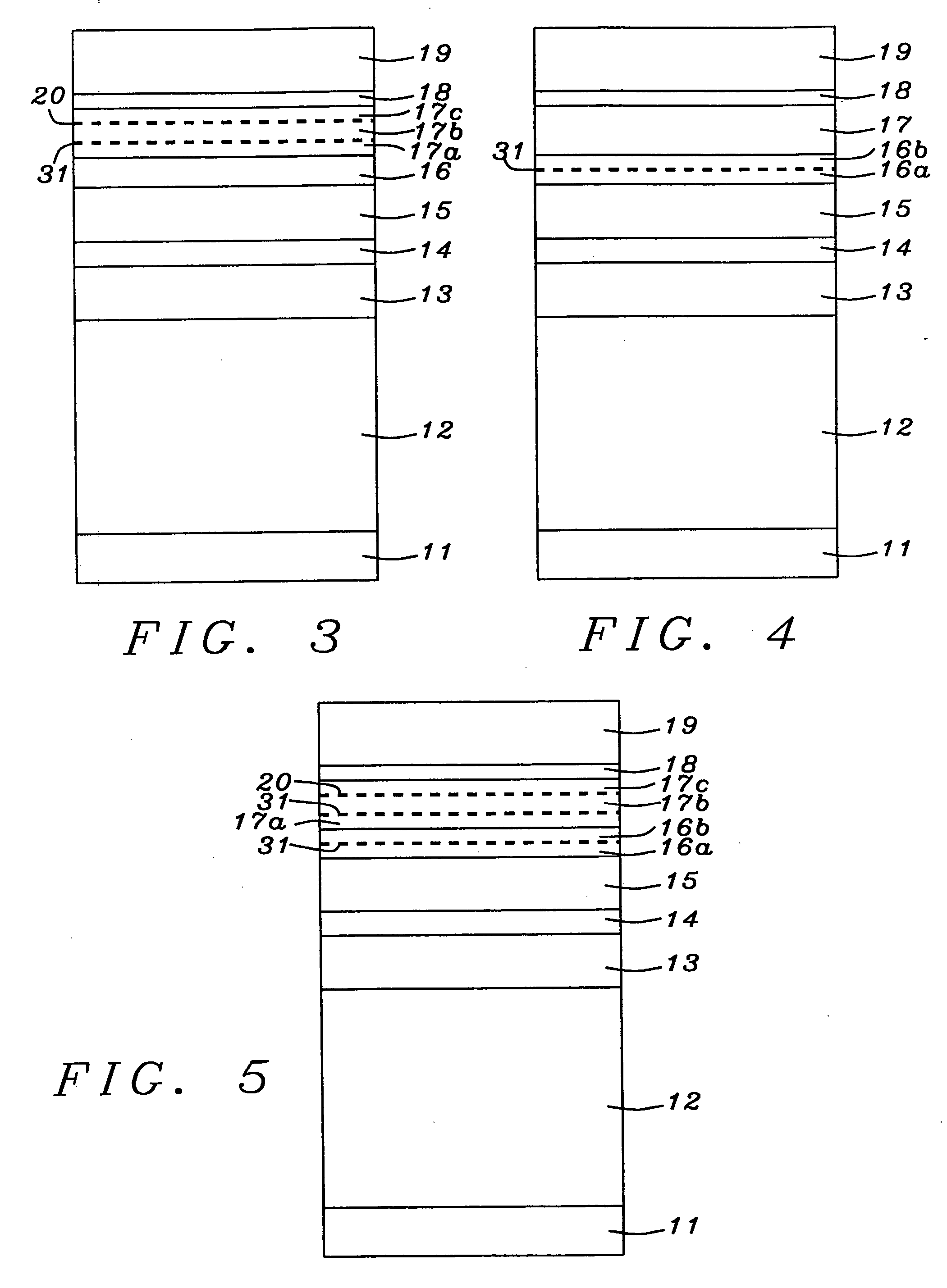
[0028] Referring now to FIG. 5, the process of the present invention begins with the provision of a substrate (not shown) on which is deposited seed layer 11. Typical materials for the latter include NiCr and Ta. The purpose of the seed layer is to provide an improved nucleating surface for antiferromagnetic layer 12 which is deposited next and which will serve as a pinning layer. Layer 12 can be MnPt, IrMn, NiMn, or similar material. The synthetic antiferromagnet, made up of layers 13, 14, and 15 (which was discussed earlier) is now deposited and becomes the pinned layer.

[0029] Following deposition of the pinned layer, in a departure from the prior art, copper sub-layer 16a is deposited to a thickness between about 5 and 20 Angstroms, less then the full thickness of the spacer. Layer 16a is then exposed to oxygen in the manner already described above so that its surface becomes equivalent to layer 31 seen earlier as part of the free layer.

[0030] This is followed by ...

2nd embodiment

2nd Embodiment

[0036] Referring now to FIG. 3, the process for this embodiment begins with the provision of a substrate (not shown) on which is deposited seed layer 11. Typical materials for the latter include NiCr and Ta. The purpose of the seed layer is to provide an improved nucleating surface for antiferromagnetic layer 12 which is deposited next and which will serve as a pinning layer. Layer 12 can be MnPt, IrMn, NiMn, or similar material. The synthetic antiferromagnet, made up of layers 13, 14, and 15 (which was discussed earlier) is now deposited and becomes the pinned layer. This is followed by the deposition of copper spacer layer 16.

[0037] Next, in a departure from prior art practice, the CoFe free layer is deposited in three stages. The first of these is sub-layer 17a which is deposited onto copper spacer layer 16 to a thickness between about 5 and 15 Angstroms. Then, copper sub-layer 31 is deposited on CoFe sub-layer 17a. The thickness of layer 31 (and other copper sub-l...

3rd embodiment

3rd Embodiment

[0042] As seen in FIG. 4, this embodiment is similar to the second embodiment for all steps up to completion of the pinned layer. Formation of the spacer layer is, however, different from the prior art:

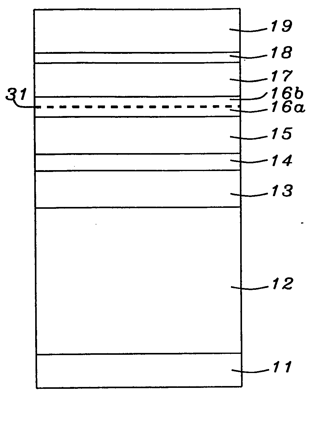
[0043] Following deposition of the pinned layer, copper sub-layer 16a is deposited to a thickness between about 5 and 20 Angstroms, less then the full thickness of the spacer. Layer 16a is then exposed to oxygen in the manner already described above so that its surface becomes equivalent to layer 31 seen earlier as part of the free layer.

[0044] This is followed by the deposition of second copper sub-layer 16b on sub-layer 31 to complete formation of the spacer layer to a total thickness between about 6 and 21 Angstroms. The remainder of the process of the second embodiment follows standard sub-processes—deposition of contacting layer 18 and cap layer 19.


PUM

PropertyMeasurementUnit
thicknessaaaaaaaaaa
thicknessaaaaaaaaaa
thicknessesaaaaaaaaaa

Abstract

It has been found that the insertion of a copper laminate within CoFe, or a CoFe / NiFe composite, leads to higher values of CPP GMR and DRA. However, this type of structure exhibits very negative magnetostriction, in the range of high −10−6 to −10−5. This problem has been overcome by giving the copper laminates an oxygen exposure treatment When this is done, the free layer is found to have a very low positive magnetostriction constant. Additionally, the value of the magnetostriction constant can be adjusted by varying the thickness of the free layer and / or the position and number of the oxygen treated copper laminates.

Description

FIELD OF THE INVENTION [0001] The invention relates to the general field of CPP GMR read heads with particular reference to controlling magnetostriction in magnetically free layers of CoFe. BACKGROUND OF THE INVENTION [0002] The principle governing the operation of most magnetic read heads is the change of resistivity of certain materials in the presence of a magnetic field (magneto-resistance or MR). Magneto-resistance can be significantly increased by means of a structure known as a spin valve where the resistance increase (known as Giant Magneto-Resistance or GMR) derives from the fact that electrons in a magnetized solid are subject to significantly less scattering by the lattice when their own magnetization vectors (due to spin) are parallel (as opposed to anti-parallel) to the direction of magnetization of their environment. [0003] The key elements of a spin valve are illustrated in FIG. 1. They are seed layer 11 on which is antiferromagnetic layer 12 whose purpose is to act a...

Claims


Application Information

Patent Timeline
Patent Type & Authority Applications(United States)
IPC IPC(8): G11B5/127G11B5/33G11B5/31G11B5/39H01F10/16H01F10/30H01F10/32H01F41/30H01L43/08H01L43/12
CPCB82Y10/00B82Y25/00B82Y40/00G01R33/093G01R33/098Y10T29/49044G11B5/3903G11B2005/3996H01F10/30H01F10/3268H01F41/305G11B5/3163
Inventor LI, MINZHANG, KUNLIANGSANO, MASASHITERUNUMA, KOICHILIAO, SIMONJU, KOCHAN
Owner HEADWAY TECH INC
Why Eureka
Try Eureka