Magnetoresistive spin valve sensor with tri-layer free layer

a technology of magnetoresistive spin valve and free layer, which is applied in the field of magnetoresistive read sensors, can solve problems such as the change of the resistance of the layered configuration, and achieve the effects of low areal resistance (ra), high mr ratio, and low free layer coercivity

Active Publication Date: 2008-02-19
HEADWAY TECH INC
View PDF17 Cites 43 Cited by
  • Summary
  • Abstract
  • Description
  • Claims
  • Application Information

AI Technical Summary

Benefits of technology

[0017]A first object of this invention is to provide a method of forming a TMR sensor that combines a high MR ratio, low free layer coercivity and a low areal resistance (RA).
[0018]A second object of the present invention is to provide a method of forming a TMR sensor that allows adjustment of its magnetostriction properties.
[0019]A third object of the present invention is to provide a method of forming a GMR sensor having a CPP configuration or a CCP CPP configuration and a low free layer coercivity, high GMR ratio and a low areal resistance.

Problems solved by technology

This polarization, in turn, affects their scattering properties within the layers and, consequently, results in changes in the resistance of the layered configuration.
Thus, one of the major challenges for the design of TMR sensors is to improve the MR ratio while keeping RA low.

Method used


Image

  • Magnetoresistive spin valve sensor with tri-layer free layer
  • Magnetoresistive spin valve sensor with tri-layer free layer
  • Magnetoresistive spin valve sensor with tri-layer free layer

Examples


Embodiment Construction

[0049]The first preferred embodiment of the present invention is a TMR sensor structure of improved areal resistance, improved free layer coercivity, improved magnetoresistive ratio (dR / R) and improved magnetostriction qualities. This improvement is obtained by the introduction of a tri-layer free layer comprising a CoFeB layer interposed between CoFe and NiFe layers.

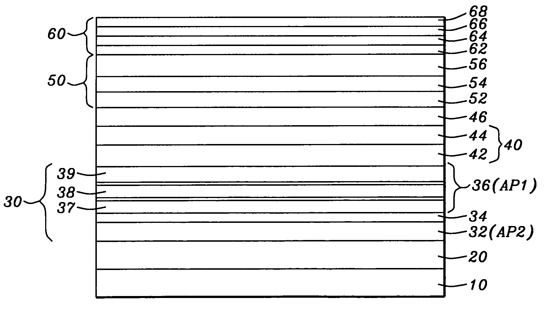
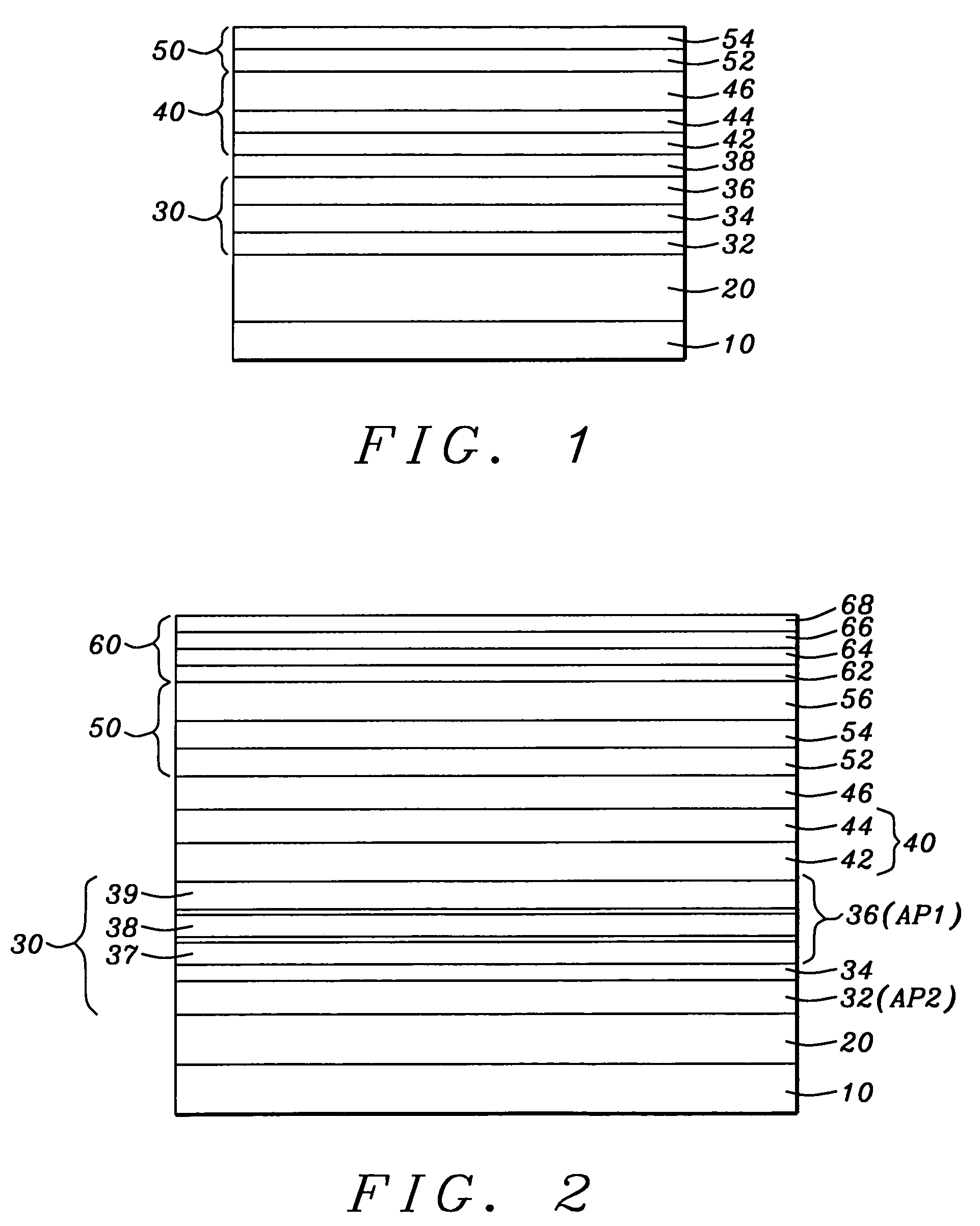
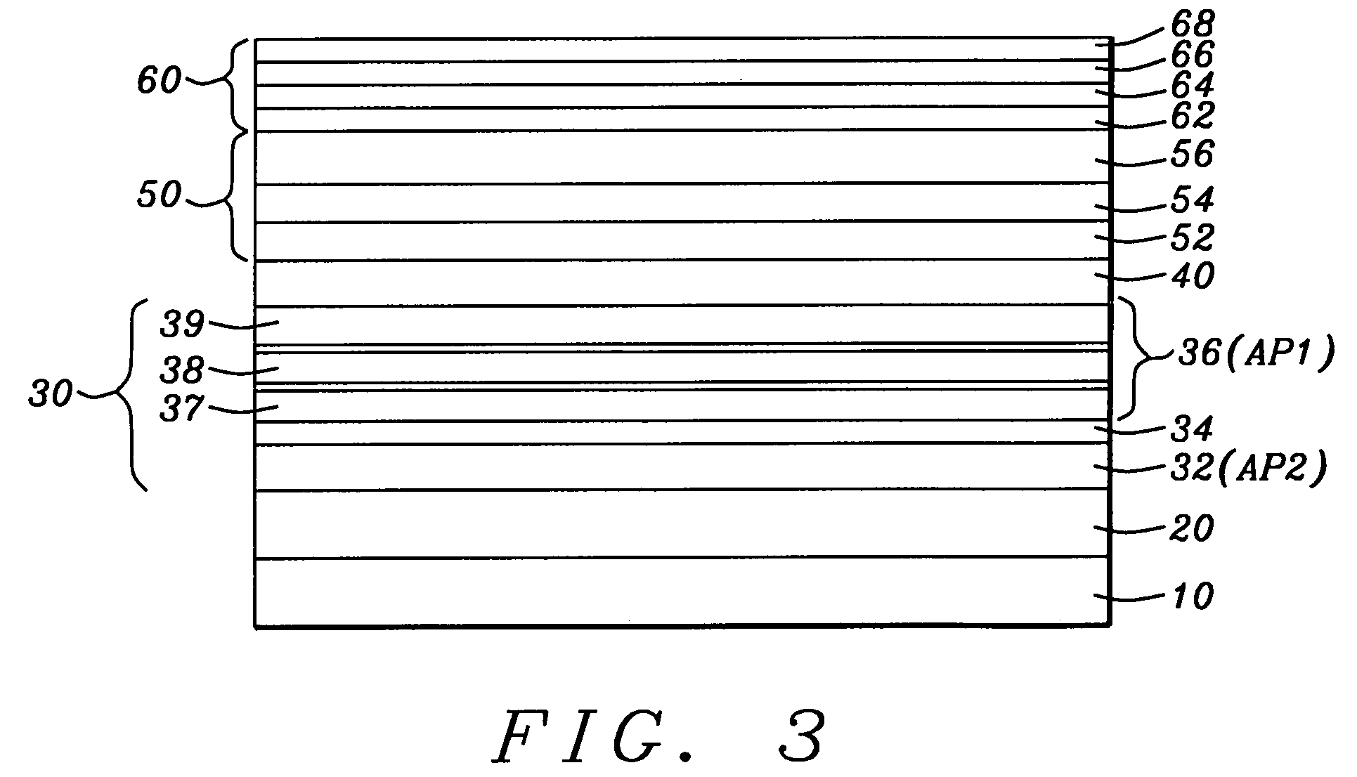
[0050]Referring first to FIG. 1, there is shown in schematic form a cross-sectional view through a vertical plane of a TMR sensor stack with conduction lead layers and magnetic biasing layers not illustrated. It is understood that the layers in the stack are most typically formed by a process of sputtering from appropriate targets, with the exception of layers that require additional processing as will be noted. Looking at the layered structure from the bottom to the top, there is shown first a seed layer (10), which can be a layer of Ta / NiCr with the Ta formed to a thickness between approximately 5 and 30 angstroms, wi...


PUM

PropertyMeasurementUnit
thicknessaaaaaaaaaa
thicknessaaaaaaaaaa
thicknessaaaaaaaaaa

Abstract

A TMR sensor, a CPP GMR sensor and a CCP CPP GMR sensor all include a tri-layered free layer that is of the form CoFe / CoFeB / NiFe, where the atom percentage of Fe can vary between 5% and 90% and the atom percentage of B can vary between 5% and 30%. The sensors also include SyAP pinned layers which, in the case of the GMR sensors include at least one layer of CoFe laminated onto a thin layer of Cu. In the CCP CPP sensor, a layer of oxidized aluminum containing segregated particles of copper is formed between the spacer layer and the free layer. All three configurations exhibit extremely good values of coercivity, areal resistance, GMR ratio and magnetostriction.

Description

BACKGROUND OF THE INVENTION[0001]1. Field of the Invention[0002]This invention relates generally to magnetoresistive read sensors and particularly to the free layer formations of such sensors operating in a tunneling magnetoresistive (TMR) configuration and current-perpendicular-to-plane GMR configurations.[0003]2. Description of the Related Art[0004]In simplest form, the usual giant magnetoresistive (GMR) read sensor consists of two magnetic layers, formed vertically above each other in a parallel planar configuration and separated by a conducting, but non-magnetic, spacer layer. Each magnetic layer is given a unidirectional magnetic moment within its plane and the relative orientations of the two planar magnetic moments determines the electrical resistance that is experienced by a current that passes from magnetic layer to magnetic layer through the spacer layer. The physical basis for the GMR effect is the fact that the conduction electrons are spin polarized by interaction with ...

Claims


Application Information

Patent Timeline
Patent Type & Authority Patents(United States)
IPC IPC(8): G11B5/127G11B5/33
CPCB82Y25/00G01R33/093Y10T29/49041Y10T29/49046Y10T29/49032Y10T428/1121Y10T29/49028
Inventor ZHAO, TONGZHANG, KUNLIANGWANG, HUI-CHUANCHEN, YU-HSIALI, MIN
Owner HEADWAY TECH INC
Why Eureka
Try Eureka