Manufacturing method of magnetoresistive effect element

a manufacturing method and magnetoresistive effect technology, applied in the manufacture of inductance/transformer/magnet, spin-exchange-coupled multilayers, magnetic bodies, etc., can solve the problem of insufficient mr ratio of the magnetoresistive effect element described in non-patent document 1 , to achieve the effect of enhancing mr ratio, high mr ratio and enhancing mr ratio

Active Publication Date: 2016-08-18
CANON ANELVA CORP
View PDF11 Cites 3 Cited by
  • Summary
  • Abstract
  • Description
  • Claims
  • Application Information

AI Technical Summary

Benefits of technology

[0007]However, the MR ratio of the magnetoresistive effect element described in Non Patent Document 1 is still not high enough. While studies on further enhancement of the MR ratio by changing the structure of the magnetoresistive effect element are in progress on the one hand, there is also a demand on the other hand for enhancing the MR ratio by changing a manufacturing method instead of the structure.
[0008]The present invention has been made to solve the above-mentioned problem. An object of the present invention is to provide a manufacturing method of a magnetoresistive effect element having a higher MR ratio than that of a conventional magnetoresistive effect element.
[0009]A first aspect of the present invention is a manufacturing method of a magnetoresistive effect element comprising: a first step of forming a tunnel barrier layer on a substrate, on a surface of which one of a magnetization free layer and a magnetization fixed layer is formed; a second step of cooling the substrate after the first step; a third step of forming an other one of the magnetization free layer and the magnetization fixed layer on the tunnel barrier layer after the second step; and a fourth step of raising a temperature of the substrate after the third step.
[0010]According to the manufacturing method of a magnetoresistive effect element of the present invention, it is possible to realize the magnetoresistive effect element having a high MR ratio by performing the step of cooling the substrate after the step of forming the tunnel barrier layer and before the step of forming either the magnetization free layer or the magnetization fixed layer on the tunnel barrier layer. Moreover, according to the manufacturing method of a magnetoresistive effective element of the present invention, it is possible to prevent dew condensation on the substrate and thereby to improve yield by performing the step of raising the temperature of the substrate after the step of forming the tunnel barrier layer and after the step of forming either the magnetization free layer (a free layer) or the magnetization fixed layer (a reference layer) on the tunnel barrier layer.

Problems solved by technology

However, the MR ratio of the magnetoresistive effect element described in Non Patent Document 1 is still not high enough.

Method used


Image

  • Manufacturing method of magnetoresistive effect element
  • Manufacturing method of magnetoresistive effect element
  • Manufacturing method of magnetoresistive effect element

Examples


first embodiment

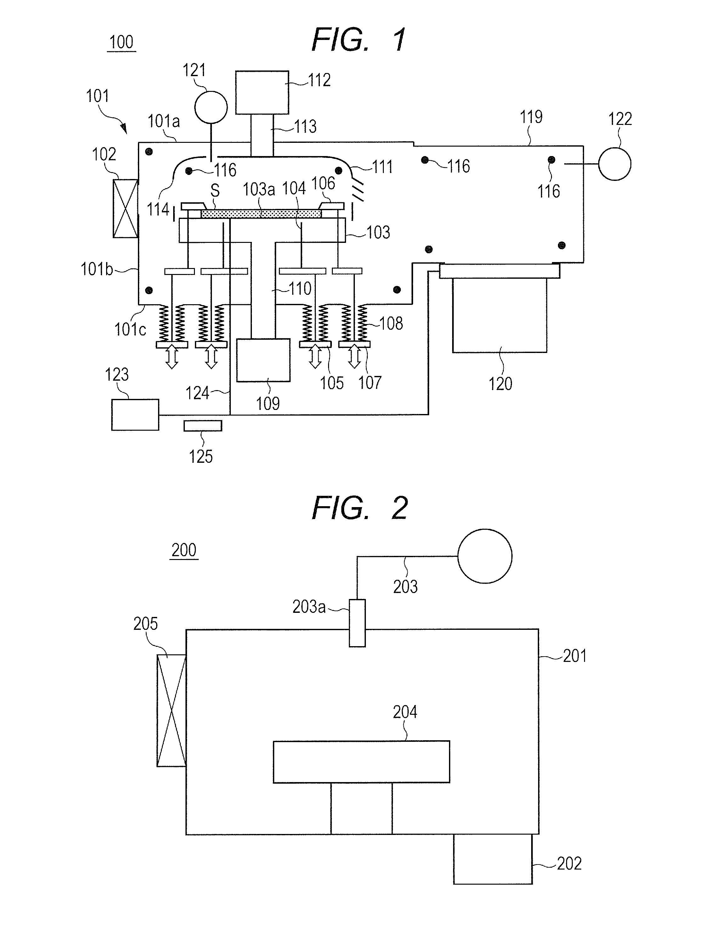
[0022]FIG. 1 is a schematic configuration diagram showing a substrate cooling device 100 of this embodiment, which serves as a substrate processing device configured to cool a substrate. The substrate cooling device 100 includes a chamber 101 and an exhaust chamber 119. An upper wall 101a of the chamber 101 is detachably provided, so that maintenance work, cleaning, and the like can be performed while detaching the upper wall 101a. A gate valve 102 is openably and closably provided to a side wall 101b of the chamber 101, so that a substrate S can be conveyed into and out of the chamber 101 through the gate valve 102. A substrate holder 103 having a substrate mounting surface 103a is provided inside the chamber 101. The substrate S can be mounted on the substrate mounting surface 103a.

[0023]The substrate holder 103 is provided with a rod-like lift pin 104 for supporting a bottom surface of the substrate S while penetrating the substrate mounting surface 103a. By using a lift pin dri...

second embodiment

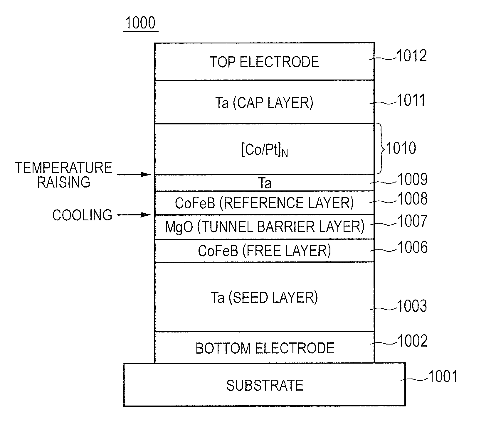
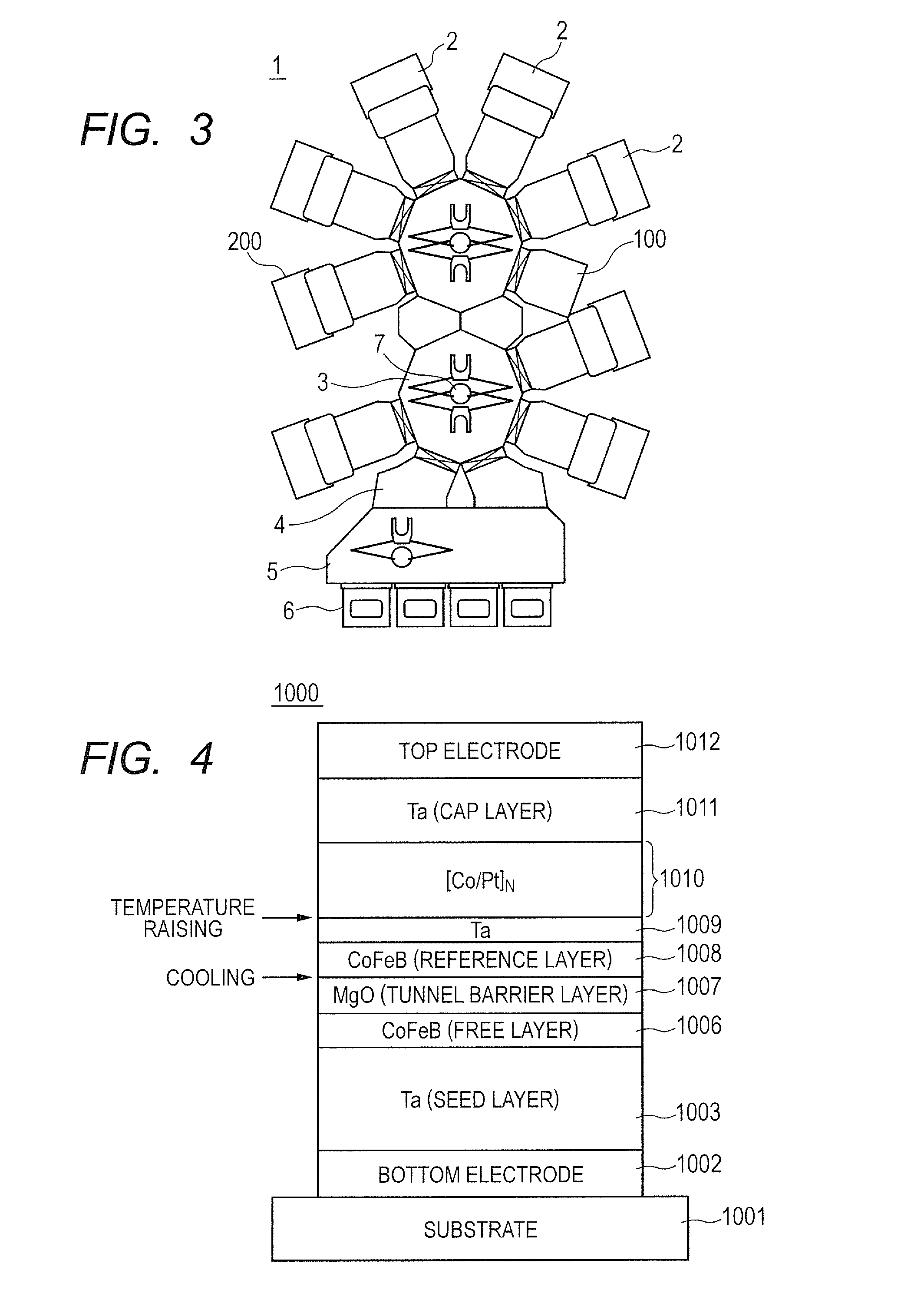
[0070]While the MTJ element 1000 according to the first embodiment has the structure (the top pin structure) in which the reference layer 1008 is provided on the tunnel barrier layer 1007, the present invention is also applicable to the structure (the bottom pin structure) in which the free layer is provided on the tunnel barrier layer. FIG. 10 is a diagram showing a flowchart of a film formation method of the MTJ element 2000 shown in FIG. 9, which represents an example of the MTJ element of the bottom pin structure.

[0071]After a substrate is carried into a given substrate processing chamber (step S31), layers up to a CoFeB layer 2007 as a reference layer are formed in a lower layer forming step (step S32). Specifically, in the lower layer forming step (step S32) of the manufacturing process of the MTJ element 2000, a bottom electrode 2002, a Ta seed layer 2003, a Ru layer 2004, a laminated body 2005 (a pin layer), a Ta layer 2006, and the CoFeB layer 2007 as the reference layer ar...


PUM


Abstract

This invention provides a manufacturing method of a magnetoresistive effect element having a higher MR ratio than a conventional element. A manufacturing method of a magnetoresistive effect element of an embodiment of the invention includes: a step of forming a tunnel barrier layer on a substrate, on a surface of which one of a magnetization free layer and a magnetization fixed layer is formed; a step of cooling the substrate after the step of forming a tunnel barrier layer; a step of forming an other one of the magnetization free layer and the magnetization fixed layer on the tunnel barrier layer after the step of cooling; and a step of raising a temperature of the substrate after the step of forming the other one of the magnetization free layer and the magnetization fixed layer.

Description

CROSS-REFERENCES TO RELATED APPLICATIONS[0001]This application is a continuation application of International Application No. PCT / JP2014 / 005682, filed Nov. 12, 2014, which claims the benefit of Japanese Patent Application Nos. 2013-237543 filed Nov. 18, 2013, 2014-082914 filed Apr. 14, 2014 and 2014-128811 filed Jun. 24, 2014. The contents of the aforementioned applications are incorporated herein by reference in their entireties.TECHNICAL FIELD[0002]The present invention relates to a manufacturing method of a magnetoresistive effect element, or more specifically, to a manufacturing method suitable for a TMR element used in an MRAM.BACKGROUND ART[0003]As a magnetoresistive effect element which changes its electric resistance depending on a magnetic field, there has been known a TMR element (also referred to as an MTJ element) adapted to store information and to detect magnetism by using a TMR (tunnel magnetoresistance) effect. The use of the MTJ elements in MRAMs and the like has be...

Claims


Application Information

Patent Timeline
Patent Type & Authority Applications(United States)
IPC IPC(8): H01L43/12H01L27/22
CPCH01F10/32H01L21/67109H01L27/222H01L43/12H01L21/68742H01F10/123H01F10/3286H01F41/302H10N50/01H10B61/00
Inventor SEINO, TAKUYAOTANI, YUICHINISHIMURA, KAZUMASA
Owner CANON ANELVA CORP
Why Eureka
Try Eureka