MRAM with super-paramagnetic sensing layer

a super-paramagnetic sensing and layer technology, applied in the direction of magnetic field controlled resistors, semi-semiconductor devices, electrical devices, etc., can solve the problems of undesired changes in the magnetic state of a half-selected cell, high switching field and difficult control, and undesirable variations in the switching threshold. , to achieve the effect of minimizing the stray field

Active Publication Date: 2010-04-13
TAIWAN SEMICON MFG CO LTD
View PDF7 Cites 4 Cited by
  • Summary
  • Abstract
  • Description
  • Claims
  • Application Information

AI Technical Summary

Benefits of technology

[0013]One objective of the present invention is to provide a MTJ based on a super-paramagentic (SP) free layer in a pinned / tunnel / SP free configuration that eliminates the problem of free layer / pinned layer coupling and the incompatibility issue for free layer materials to have a low Hc and yet produce a high MR ratio for the MTJ.
[0018]In either embodiment, the storage layer may be comprised of laminated layers as in a synthetic structure. Furthermore, the pinned layer may have a synthetic anti-parallel (SyAP) configuration to minimize the stray field from pinned layer magnetization.

Problems solved by technology

Due to variations in MTJ size and shape that affect the switching field of a free layer, a magnetic state in a half-selected cell may be undesirably altered when writing to a selected cell.
As a result, MTJ cell differences can make the switching field highly variable and difficult to control.
Variations in this coupling cause undesirable variations in the switching threshold.
A second problem with conventional MTJs is that magnetic charges at the edges of the pinned layer produce a bias and variations in this bias also lead to variations in the switching threshold.
Another issue is that in order to achieve reliable switching behavior, the free layer is generally limited to materials with small coercivity (Hc).
However, materials with small Hc typically do not produce a sufficiently high magnetoresistive (MR) ratio to meet high performance requirements.
On the other hand, materials such as CoFeB and CoFe with high Fe content that are desirable for high MR ratios do not have the necessary magnetic softness for low coercivity.
However, as the device has no hysteresis, information cannot be stored therein.

Method used


Image

  • MRAM with super-paramagnetic sensing layer
  • MRAM with super-paramagnetic sensing layer
  • MRAM with super-paramagnetic sensing layer

Examples


Embodiment Construction

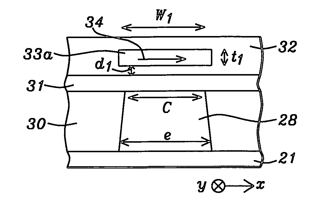
[0032]The present invention is a MRAM structure comprised of a MTJ having a ferromagnetic layer and a super-paramagnetic (SP) free layer that are separated by a tunneling layer in a pinned / tunnel / SP free configuration. The MRAM also includes a storage layer (for storing digital information) that is separated from the MTJ, disposed on the top surface of the MTJ, or formed at the bottom surface of the MTJ. The drawings are provided by way of example and are not intended to limit the scope of the invention. Note that only one MTJ is depicted in the drawings but it should be understood that there are a plurality of MTJs in an array that has multiple rows and columns in a memory device such as an MRAM chip. Furthermore, the MTJ may have a pinned / tunnel / SP free configuration or an SP free / tunnel / pinned configuration. The super-paramagnetic free layer has no (or very little) residual magnetization in the absence of an external field and has a magnetization substantially proportional to an ...


PUM


Abstract

An MRAM is disclosed that has a MTJ comprised of a ferromagnetic layer with a magnetization direction along a first axis, a super-paramagnetic (SP) free layer, and an insulating layer formed therebetween. The SP free layer has a remnant magnetization that is substantially zero in the absence of an external field, and in which magnetization is roughly proportional to an external field until reaching a saturation value. In one embodiment, a separate storage layer is formed above, below, or adjacent to the MTJ and has uniaxial anisotropy with a magnetization direction along its easy axis which parallels the first axis. In a second embodiment, the storage layer is formed on a non-magnetic conducting spacer layer within the MTJ and is patterned simultaneously with the MTJ. The SP free layer may be multiple layers or laminated layers of CoFeB. The storage layer may have a SyAP configuration and a laminated structure.

Description

FIELD OF THE INVENTION[0001]The invention relates to a MRAM structure having a magnetic tunnel junction (MTJ) with one ferromagnetic layer and one super-paramagnetic free layer which are separated by a tunneling layer. Digital information is read out from a separate storage layer by the MTJ sensing element.BACKGROUND OF THE INVENTION[0002]Magnetic random access memory (MRAM) that incorporates a MTJ as a memory storage device is a strong candidate to provide a high density, fast (1-30 ns read / write speed), and non-volatile solution for future memory applications. An MRAM array is generally comprised of an array of parallel first conductive lines on a horizontal plane, an array of parallel second conductive lines on a second horizontal plane spaced above and formed in a direction perpendicular to the first conductive lines, and a MTJ interposed between a first conductive line and a second conductive line at each crossover point. A first conductive line may be a word line while a secon...

Claims


Application Information

Patent Timeline
Patent Type & Authority Patents(United States)
IPC IPC(8): H01L29/94
CPCH01L43/08H10N50/10
Inventor WANG, PO-KANGGUO, YIMINHORNG, CHENGMIN, TAITONG, RU-YING
Owner TAIWAN SEMICON MFG CO LTD
Why Eureka
Try Eureka