Magnetoresistance effect element
a technology of magnetic effect and element, applied in the field of magnetic effect element, can solve the problems of varying mr ratio affecting the rewriting speed, etc., and achieves the effects of reducing the size of the device, high thermal disturbance resistance, and high spin polarization
- Summary
- Abstract
- Description
- Claims
- Application Information
AI Technical Summary
Benefits of technology
Problems solved by technology
Method used
Image
Examples
first embodiment
(First Embodiment)
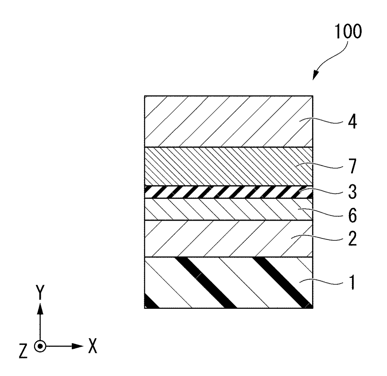
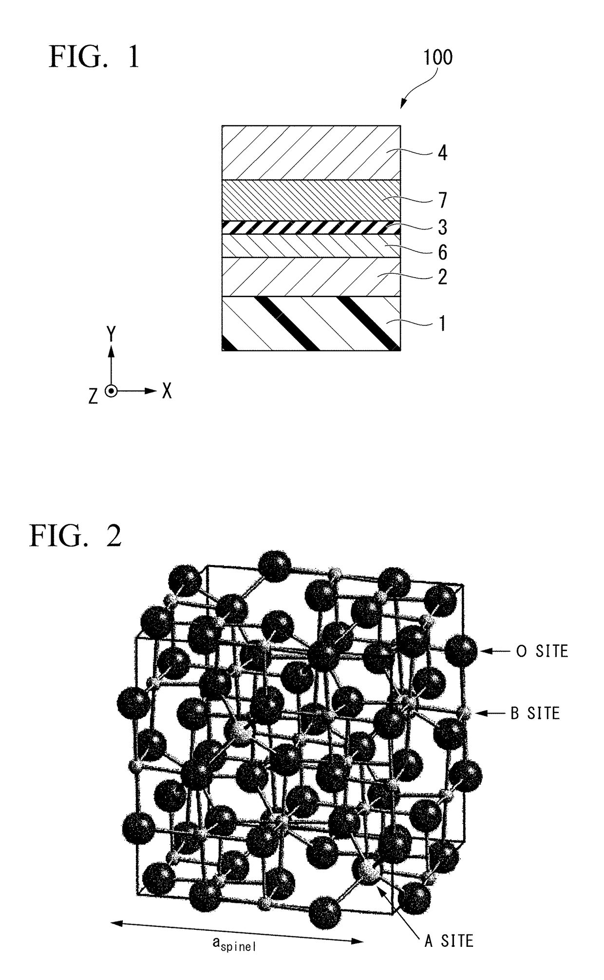
[0044]A magnetoresistance effect element 100 according to a first embodiment will be described below. The magnetoresistance effect element 100 has a laminate in which an underlayer 2, a first ferromagnetic metal layer 6, a tunnel barrier layer 3, and a second ferromagnetic metal layer 7 are laminated in that order. The underlayer 2 is made of TiN, VN, or a mixed crystal thereof. The tunnel barrier layer 3 is made of a compound having a spinel structure and represented by the following composition formula (1).
AxGa2Oy (1)
[0045]where, A is a non-magnetic divalent cation and represents a cation of at least one element selected from the group consisting of magnesium, zinc, and cadmium, x is a number that satisfies 0<x≦2, and y is a number that satisfies 0<y≦4.
(Basic Structure)
[0046]In the example shown in FIG. 1, the magnetoresistance effect element 100 is provided on a substrate 1 and has a structure in which the underlayer 2, the first ferromagnetic metal layer 6, t...
second embodiment
(Second Embodiment)
[0091]A difference between a second embodiment and the first embodiment is only a method of forming a tunnel barrier layer. In the first embodiment, the tunnel barrier layer is formed by repeatedly performing formation of a metal film, oxidation, formation of a metal film, and oxidation. In the second embodiment, in the oxidation process, a temperature of the substrate is cooled to −70 to −30° C., and then oxidation is performed. When the substrate is cooled, a temperature gradient occurs between the substrate and a vacuum or between the substrate and plasma. First, when oxygen is brought into contact with a surface of the substrate, it reacts with a metal material and oxidation occurs.
[0092]However, since the temperature is low, oxidation does not proceed. Accordingly, it is easy to adjust an amount of oxygen in the tunnel barrier layer. In addition, when the temperature gradient is formed, it is easy to adjust epitaxial growth (lattice-matched growth). Since cry...
example 1
[0099]An example of a method of producing the magnetoresistance effect element according to the first embodiment will be described below. A film was formed on the substrate 1 on which a thermally oxidized silicon film was provided using a magnetron sputtering method. First, 10 nm of TiN was formed on an upper surface of the substrate 1 as the underlayer 2. The underlayer 2 was formed by a reactive sputtering method in which a Ti target was used as a target and a mixed gas containing Ar and nitrogen (volume ratio 1:1) was used as a sputtering gas. Next, TiN of the underlayer 2 was polished to 4 nm by CMP. Further, 2 nm of FeB was formed on the underlayer 2 as the first ferromagnetic metal layer 6.
[0100]Next, the tunnel barrier layer 3 was formed on the first ferromagnetic metal layer 6. A method of forming the tunnel barrier layer 3 will be described. A target having an MgGa2 alloy composition was sputtered to form an MgGa2 film of 0.5 nm. Then, the specimen was moved into an oxidati...
PUM
 Abstract
Description
Claims
Application Information
 - R&D
- Intellectual Property
- Life Sciences
- Materials
- Tech Scout
- Unparalleled Data Quality
- Higher Quality Content
- 60% Fewer Hallucinations
Browse by: Latest US Patents, China's latest patents, Technical Efficacy Thesaurus, Application Domain, Technology Topic, Popular Technical Reports.
© 2025 PatSnap. All rights reserved.Legal|Privacy policy|Modern Slavery Act Transparency Statement|Sitemap|About US| Contact US: help@patsnap.com


