Printing a mask with maximum possible process window through adjustment of the source distribution

a technology of source distribution and mask, applied in the field of manufacturing processes, can solve the problems of limited resolution of lithography tools, a challenge to improve ic manufacture, image distortion becomes a significant problem, etc., and achieve the effect of minimizing loss

Inactive Publication Date: 2006-06-06
GLOBALFOUNDRIES INC
View PDF5 Cites 45 Cited by
  • Summary
  • Abstract
  • Description
  • Claims
  • Application Information

AI Technical Summary

Benefits of technology

[0024]Another aspect of the teachings herein includes a method for minimizing a loss in an integrated process window, the loss resulting from perturbations in a plurality of masks, each mask containing features for printing a common shape, where the perturbations span the range of errors that must realistically be expected when the features are fabricated on a typical mask using a practical mask-making process, the method includes illuminating each mask with a source of light from different directions according to a common window, wherein illumination is such that intensities of incident beams of light provide a largest possible integrated process window for printing the common shape within the allowed range using every perturbed mask, with the same exposure and focal range used for each mask, the integrated process window defined in terms of an allowed range for defining the common shape, wherein the largest possible integrated process window comprises an integrated range of dose and focal variations for printing the common shape without causing the printed common shape to depart from the allowed range.

Problems solved by technology

When the critical dimensions (CDs) of a desired IC pattern approach the resolution of a lithographic system (defined as the smallest dimensions that can be reliably printed by the system), image distortions become a significant problem.
Currently, the limited resolution of lithography tools poses a challenge to improvements in IC manufacture.
Although a larger NA permits smaller features to be printed, in practice NA is limited by depth-of-focus requirements, by polarization and thin-film effects, by the finite refractive index of the medium (usually air) at the lens exit, and by limitations in lens design.
However, the publication shows that the sharpness of the focused image does not always correlate with the overall lithographic quality, since a small sacrifice in exposure latitude at best-focus can yield a large increase in depth-of-focus (DOF).
Solving for a maximal integrated ED-window is problematic.
That is, the overall performance of the lithographic process is limited to the performance for the weakest feature.
These complications limit the reliability of heuristic methods for optimizing lithographic sources over extended focal ranges.
However, such equality or band constraints would predictably require adjustment on an ad-hoc or iteration-by-iteration basis, since the depth-of-focus and exposure latitude tradeoff is highly variable from pattern to pattern, and therefore difficult to predict.
However, and as with the other methods discussed above, images improved by heuristic methods are not guaranteed to meet standard lithographic criteria for optimal behavior through the depth-of-focus.
For example, lithographic performance is customarily considered to be limited by the quality of the least robust printed feature or CD (i.e., the relevant criterion is whether or not every feature is printed within tolerance; if one feature fails, the successful performance of all other features is effectively irrelevant).
Unfortunately, a filtering algorithm that emphasizes features with minimal focus and exposure sensitivity can underemphasize the weakest (and therefore most critical) features in the image.
Although adjustments could be introduced on an ad-hoc basis to deal with such limitations, these typically do not directly address the problem.
With heuristic algorithms, one must usually expect such difficulties will arise, and performance will typically become less reliable when the heuristic adjustments are made more abstract (i.e., when the adjustments do not directly embody the features of the problem which must be solved).
On the other hand, standard general-purpose methods for optimization, though non-heuristic, are based on refinement of an initial starting design, and so are limited by the quality of this initial design (i.e., the solutions provided are usually no better than the particular local optimum associated with the design used to start optimization).
Some general-purpose optimization methods, for example genetic algorithms, do attempt to search beyond the initial local optimum, but there is no guarantee that they will find the global optimum.
This is particularly true when more than a few variables are involved, since the potential search space becomes immense.
Heuristic methods in some sense consider the properties of the entire search space, but they do so in an uncertain way, and they also do not guarantee that the globally optimum solution is found.
However, these algorithms leave room for improvement.
For example, one would usually expect source weightings that are chosen by heuristic methods to produce appreciable CD errors; correction of these errors using known techniques (e.g. using an optical proximity correction (OPC) program) will in turn change the behavior of the image, and there is no guarantee that iterated cycles of heuristic source optimization and OPC adjustment will converge to an optimal solution.
Although heuristic algorithms can deliver better lithographic images than earlier techniques, the required adjustments to same are not conducive to routine use.

Method used


Image

  • Printing a mask with maximum possible process window through adjustment of the source distribution
  • Printing a mask with maximum possible process window through adjustment of the source distribution
  • Printing a mask with maximum possible process window through adjustment of the source distribution

Examples


Embodiment Construction

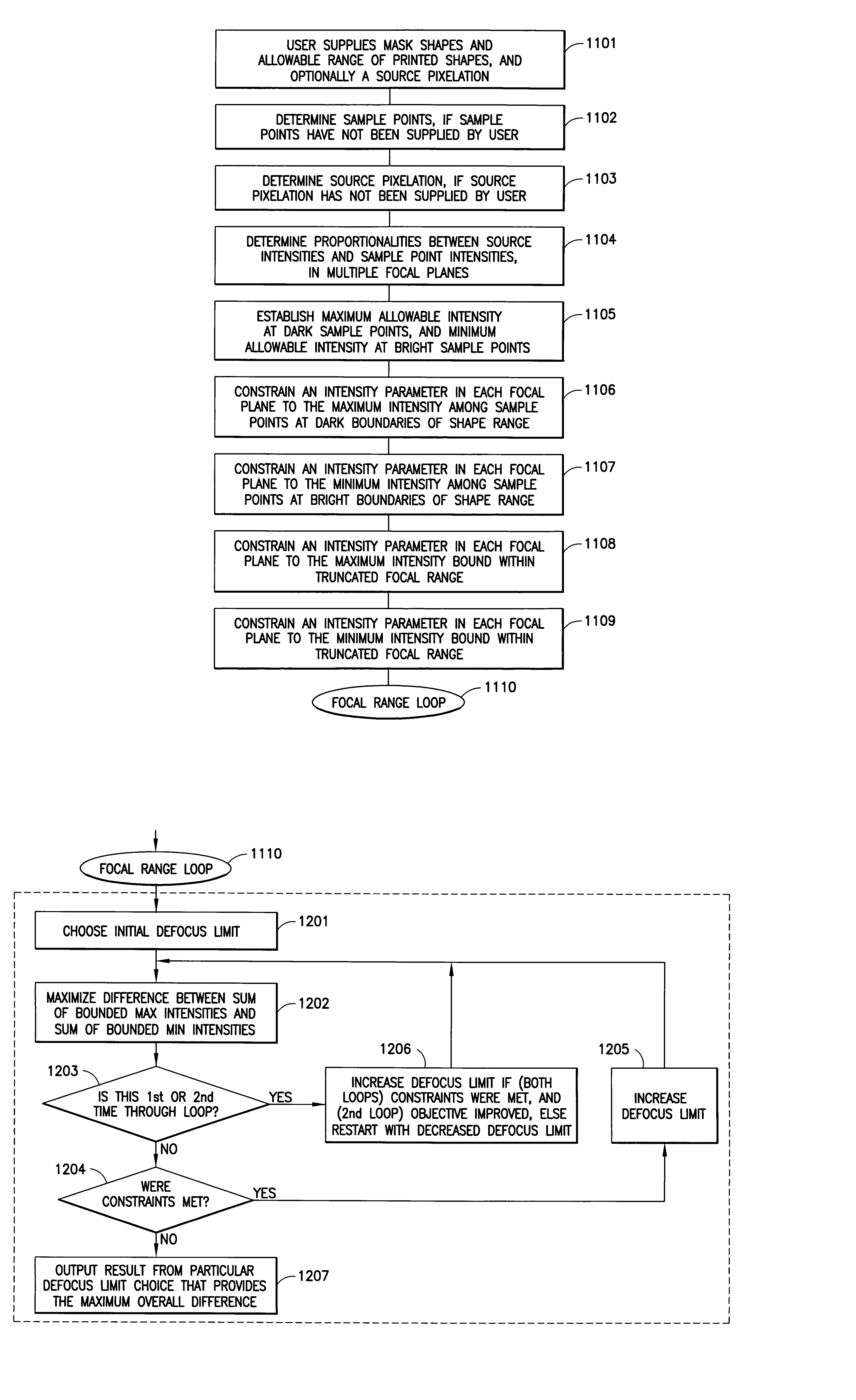
[0042]Disclosed herein are methods and apparatus for maximizing the process window through adjustment of the source distribution.

[0043]As used herein, the process window is defined as a set of limits or tolerances for the various imaging parameters. The process window takes into account the extremes of the range of lengths and widths that are allowed for the shapes, and the range of dose and focus variations which print all shapes within the allowed extremes. In many cases, one set of shape limits corresponds to underexposed print conditions, and another set to overexposed conditions. Sample points may be used to delineate the limits of allowable shapes according to two-dimensional criteria.

[0044]An optimum source pattern is expressed as a list of optimum values for the intensity of light that should be input to the mask from each possible illuminating direction. The possible illuminating directions (also referred to as “source directions”) are defined using a gridding of direction ...


PUM

PropertyMeasurementUnit
repeat distanceaaaaaaaaaa

Abstract

A lithographic mask is illuminated with light from different directions such that intensities of a plurality of incident beams of light provide a largest possible integrated process window defined in terms of an allowed range for defining shapes. Constrained sets of intensity parameters are imposed. A first set of intensity parameters represents maximum possible intensities that can be permitted for overexposed tolerance positions. A second set of intensity parameters represents minimum possible intensities that can be permitted for underexposed tolerance positions. Optimum source intensities of incident beams are defined using a linear program and constraints. The optimum source intensities maximize an integrated range of dose and focal variations without causing printed shapes to depart from the allowed range. Apparatus are detailed and variations are described.

Description

TECHNICAL FIELD OF THE INVENTION[0001]This invention relates to manufacturing processes that project high resolution images by illuminating a mask, and in particular to methods for maximizing the manufacturing process window by adjusting the illumination on the mask.BACKGROUND OF THE INVENTION[0002]Optical lithography has been widely used in the formation of structures included in integrated circuit (IC) chips. Reductions in the size of structures within IC chips have increased the demands placed upon optical lithography systems.[0003]Many methods have been developed to compensate for the image degradation that occurs when the resolution of optical lithography systems approaches the critical dimensions (CD's) of desired lithographic patterns. Critical dimension (CD) refers to the feature size and spacing between features and feature repeats (pitch) that are required by the design specifications, and that are critical for the proper functioning of the devices on a chip. When the crit...

Claims


Application Information

Patent Timeline
Patent Type & Authority Patents(United States)
IPC IPC(8): G03B27/72G03B27/32G03F7/20H01L21/027
CPCG03F7/70125
Inventor ROSENBLUTH, ALAN EDWARD
Owner GLOBALFOUNDRIES INC
Why Eureka
Try Eureka