Display identification system and display device

a display identification and display technology, applied in the field of display identification systems and display devices, can solve the problems of not being able to identify each individual display and the display, and achieve the effect of accurately specified and displayed

Inactive Publication Date: 2014-02-27
SAMSUNG ELECTRONICS CO LTD
View PDF6 Cites 50 Cited by
  • Summary
  • Abstract
  • Description
  • Claims
  • Application Information

AI Technical Summary

Benefits of technology

[0014]According to aspects of the exemplary embodiments, a different specific signal for each display may be combined with a signal for driving a backlight of each display. Accordingly, an output light of the backlight is luminance-modulated. By analyzing an optical signal obtained by the luminance modulation by using a light pen, a display toward which the light pen points may be specified. Also, in an interactive white board (IWB) including a plurality of displays, a display toward which a light pen points may be accurately specified and an input result by the light pen may be accurately displayed on the specified display.

Problems solved by technology

Accordingly, in a conventional technique of using an IWB having a plurality of displays which are the same kind and which are arranged side by side, it is not possible to identify each individual display.
In addition, when a light pen input method is used, it is not possible to identify a display on which an input by a light pen should be displayed.

Method used


Image

  • Display identification system and display device
  • Display identification system and display device
  • Display identification system and display device

Examples


Embodiment Construction

[0023]Hereinafter, the present disclosure will be described in detail by explaining exemplary embodiments with reference to the attached drawings. Like reference numerals in the drawings denote like elements. Expressions such as “at least one of,” when preceding a list of elements, modify the entire list of elements and do not modify the individual elements of the list.

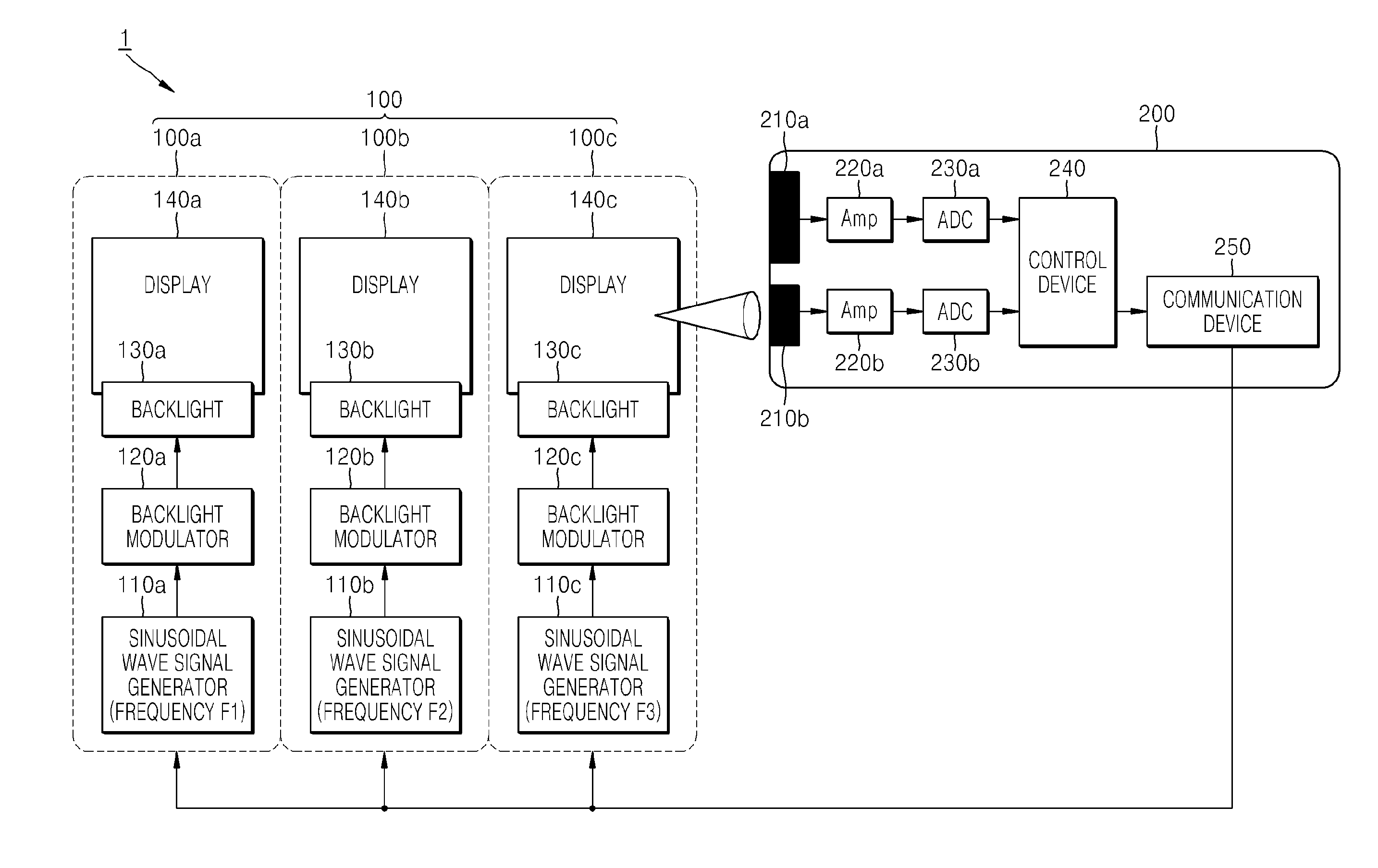
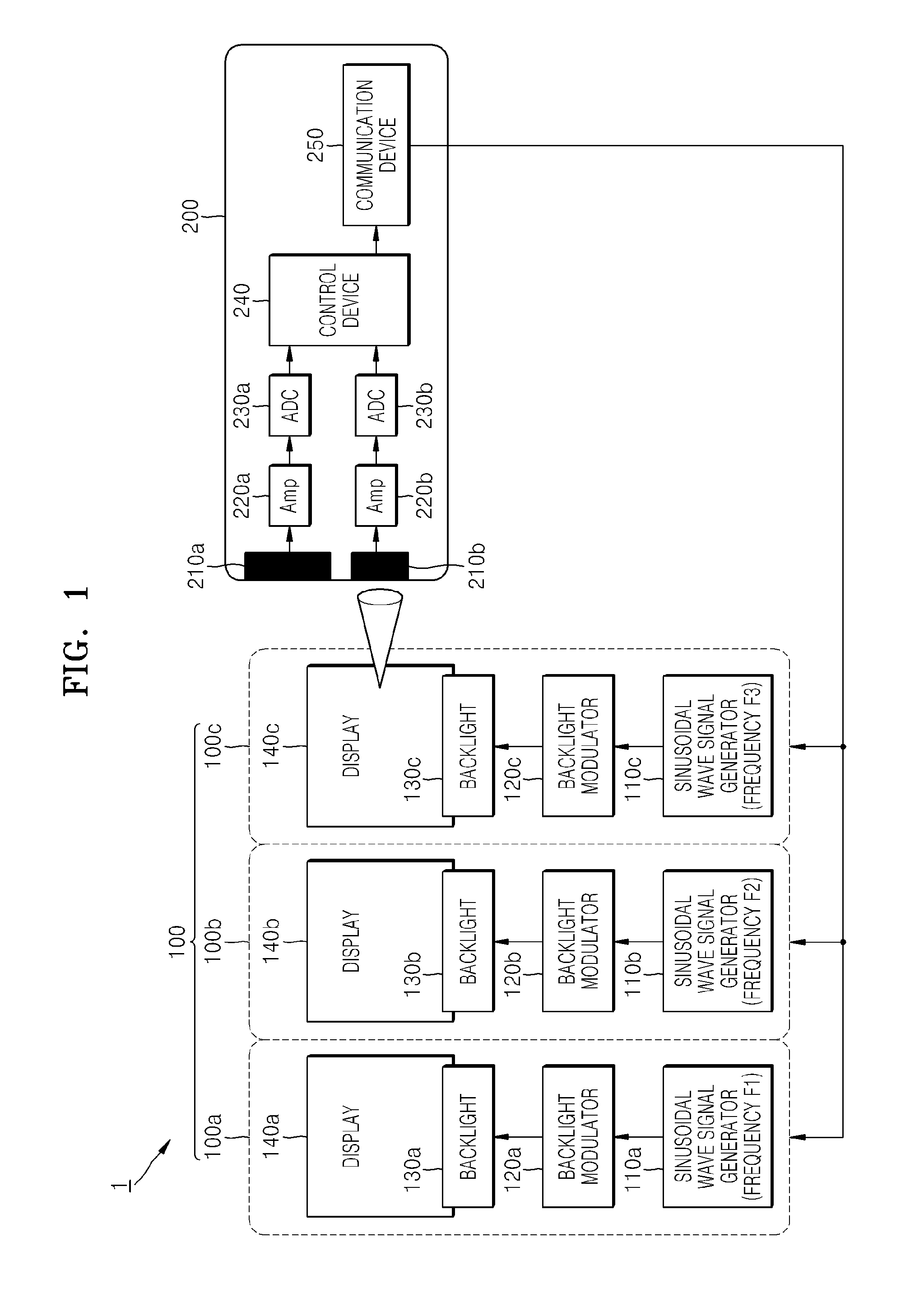
[0024]FIG. 1 is a block diagram illustrating an example of a hardware configuration of a display identification system 1 according to an exemplary embodiment.

[0025]As illustrated in FIG. 1, the display identification system 1 includes a plurality of display devices 100 and an identification device 200 for identifying the plurality of display devices 100.

[0026]In FIG. 1, three display devices, that is, a first display device 100a, a second display device 100b, and a third display device 100c, are arranged side by side, thus forming a large screen interactive white board (IWB). It is understood that more or less than th...


PUM


Abstract

A display identification system includes: a plurality of display devices, each of the display devices having a light source; and an identification device configured to identify the plurality of display devices. Each of the plurality of display devices includes a configured to perform luminance modulation to luminance-modulate an output light of the corresponding light source in a predetermined range, by combining a specific signal, which is different for each of the display devices, with a driving signal of the corresponding light source. The identification device includes: a receiver configured to receive an optical signal obtained by performing the luminance modulation; and an identification device configured to identify the plurality of display devices based on the optical signal received by the receiver.

Description

CROSS-REFERENCE TO RELATED PATENT APPLICATIONS[0001]This application claims the benefit of Japanese Patent Application No. 2012-184315, filed on Aug. 23, 2012, in the Japanese Intellectual Property Office, and Korean Patent Application No. 10-2013-0052753, filed on May 9, 2013, in the Korean Intellectual Property Office, the disclosures of which are incorporated herein in their entirety by reference.BACKGROUND[0002]1. Field[0003]The present disclosure relates to a display identification system and a display device.[0004]2. Description of the Related Art[0005]Recently, with the increase in production of mobile electronic devices, a touch screen input method in which an input operation is performed by touching a screen with a finger or a touch pen, in addition to a conventional input method using a keyboard or a mouse, has become widely used.[0006]A light pen may be mounted with a camera as a kind of touch pen. The light pen receives light corresponding to a specific pattern formed on...

Claims


Application Information

Patent Timeline
Patent Type & Authority Applications(United States)
IPC IPC(8): G06F3/0354
CPCG06F3/03545
Inventor YOKOI, ATSUYACHOI, SANG-ON
Owner SAMSUNG ELECTRONICS CO LTD
Why Eureka
Try Eureka