Fiber Optic Connector

a fiber optic connector and connector technology, applied in the field of fiber optic connectors, can solve the problems of difficult access to the vertical latch, and difficult disconnection of the connector from the adaptor, and achieve the effects of simple servicing, easy disassembly and assembly, and easy rotation of the connector

Active Publication Date: 2014-02-27
BIOGLAN IRELAND R&D LTD
View PDF1 Cites 49 Cited by
  • Summary
  • Abstract
  • Description
  • Claims
  • Application Information

AI Technical Summary

Benefits of technology

[0013]In an embodiment, a fiber optic connector latch mechanism is releasably mountable on each of two opposing faces of the connector body. A transceiver device enables transmit and receive signals to be passed to and from the same device with a two port connection interface in an optical network. Where multiple connection points are present in the network a requirement to switch or cross-connect polarity of the connector ports can be met with the present connector by fitting the connector latch mechanism to either the bottom or to the top of the connector body. This results in the switch of the fiber ports of the connector without requiring a separate specific replacement patch cord connector; either straight (non-crossed) patch cord or crossed patch cord. This feature allows ease of conversion of a crossed polarity patch cord to a straight patch cord in optical networks.
[0014]The latch mechanism of a further embodiment further comprises a mounting spigot including one or more anti-rotation side flanges, the mounting spigot and the side flanges are configured for selectable location in first and second mounting sockets provided in the said two faces of the connector body, the mounting spigot and the said flange being configured to engage with the respective mounting socket to secure the latch mechanism to the connector body and hinder rotation of the connector.
[0015]In this arrangement the adaptor and connector are protected from rotation and external torque from optical fiber so the mounting and anti-rotation features this arrangement can add rigidity to the connector and adaptor package.
[0016]In an embodiment the latch mechanism is further configured for actuation in a direction towards the connector body, the latch mechanism being moveable between an engagement position at a first separation from the connector body and a release position at a second, smaller separation from the connector body in which the latch mechanism is disengaged from the adaptor sockets. The vertical movement of the latch mechanism provides an alternative disengagement technique and can be useful in space limited applications and situations.
[0017]The removal and relatching of connectors during maintenance and reconfiguration becomes a simple servicing operation requiring servicing personnel to carry minimal tools or equipment.
[0018]The latch mechanism of the embodiment is mounted on a resilient member for movement between engaged and released positions. In particular, this allows the user to latch the adaptor within the connector in a floating free position raised above the connector body and to compress the latch in a vertical plane to disengage the adaptor from the connector. This can mean fewer latching parts and components.

Problems solved by technology

In high density applications connectors can be stacked one on another, making access to a vertical latch, and the disconnection of a connector from an adaptor, very difficult.

Method used


Image

  • Fiber Optic Connector
  • Fiber Optic Connector
  • Fiber Optic Connector

Examples


Embodiment Construction

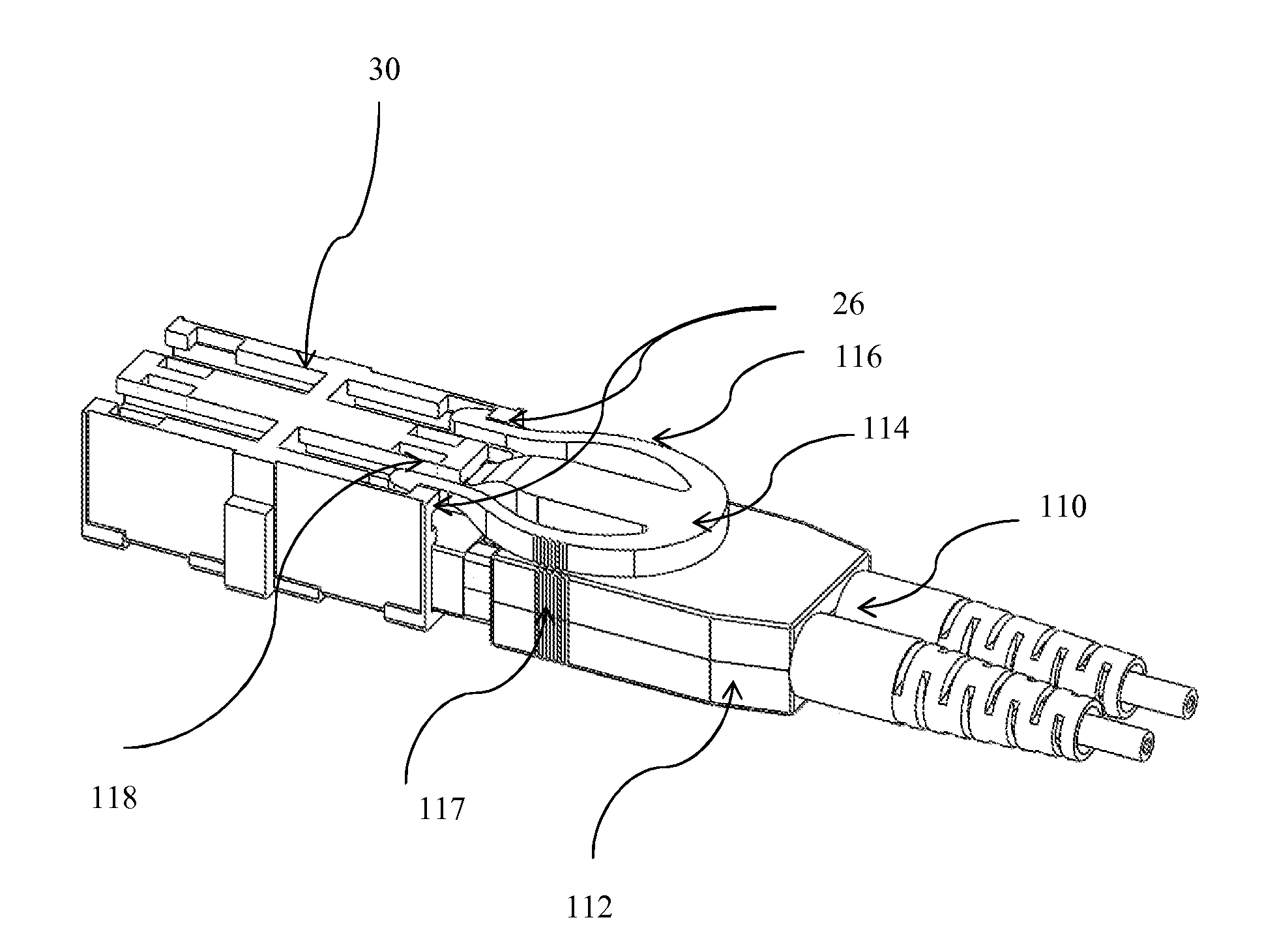
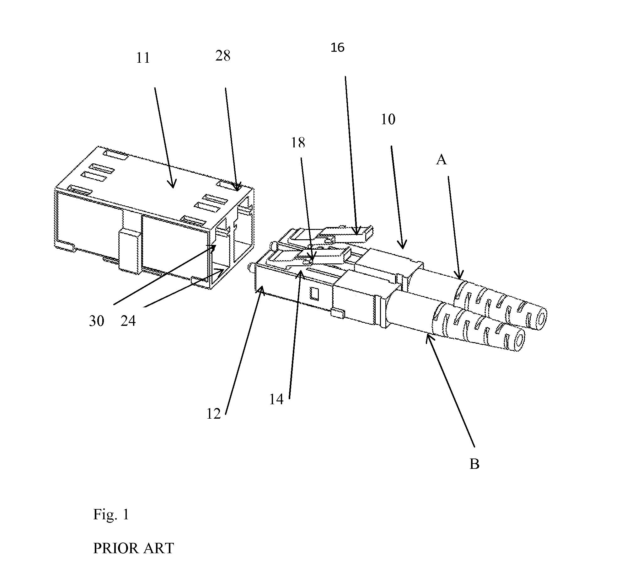
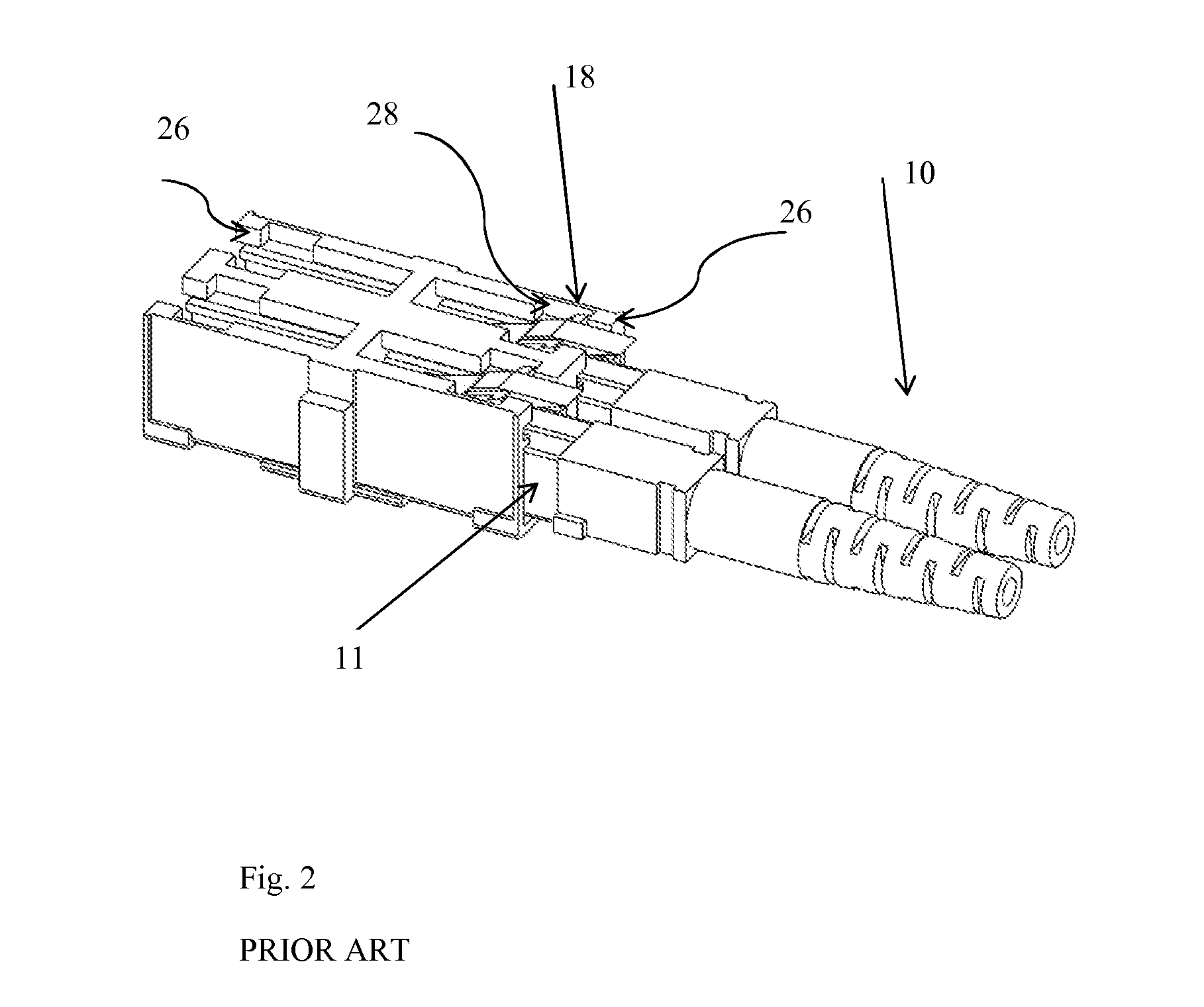
[0033]Referring now to FIGS. 1 and 2, there is shown an LC connector 10. The connector 10 comprises an elongate body 12 configured to receive and terminate two optical fibers A, B, and a latch mechanism 14. The latch mechanism 14 comprises a latch arm 16, mounted on an upper surface and at the connection end of the body 12. The latch arm 16 is sprung or biased away from the body 12 in a vertical direction. Each latch arm 16 includes a pair of latch retention lugs 18 extending laterally either side of each of the arms 16. The adaptor 11 to which the connector 10 is to be mated comprises an elongate body 22 bounding an opening 24. The opening 24 corresponds in size and shape to a connector body 12 so as to receive and terminate two optical fibers. The elongate body 22 includes at least one pair of retention shoulders 26 and at least one retention cavity 28. The retention shoulders 26 are formed as part of an indent or recess in a channel 30 or keyway within the adaptor 11. The latch r...


PUM


Abstract

A fiber optic connector arranged to be releaseably connected to a fiber optic adaptor. The fiber optic connector includes a body configured to receive and terminate two optical fibers, and a latch mechanism provided on the body. The latch mechanism is configured for releasable engagement with each of two sockets of the fiber optic adaptor. The latch mechanism of the fiber optic connector is configured for actuation in a direction laterally across the body.

Description

BACKGROUND[0001]1. Field[0002]The present application relates to a fiber optic connector. The present application also relates to a fiber optic adaptor unit comprising a fiber optic adaptor and a fiber optic connector.[0003]2. Related Art[0004]Fiber optic connections such as patch cords and interconnects are known to be made with a standard LC (Lucent Technology) Connector incorporating a latch operating in a vertical plane. In use, the user actuates the connector by depressing the connector latch in a direction vertically towards the body to disengage the connector from a corresponding adaptor. Vertical action depressing the latch allows separation of the fiber optic connector from the adaptor.SUMMARY[0005]According to a first aspect of the present application, a fiber optic connector is provided that is releasably connected to a fiber optic adaptor. The fiber optic connector includes a body configured to receive and terminate two optical fibers and a latch mechanism provided on th...

Claims


Application Information

Patent Timeline
Patent Type & Authority Applications(United States)
IPC IPC(8): G02B6/36
CPCG02B6/36G02B6/3825G02B6/3831G02B6/3878G02B6/3879G02B6/3893G02B6/4246G02B6/4292
Inventor LIMBERT, MARK JOHNPETERS, CHRISTOPHER RUSSEL
Owner BIOGLAN IRELAND R&D LTD
Why Eureka
Try Eureka