Exhaust emission control system of internal combustion engine and exhaust emission control method

an emission control system and internal combustion engine technology, applied in the direction of electrical control, exhaust treatment electric control, separation process, etc., can solve the problem of high cost of urea concentration sensor, and achieve the effect of reducing cos

Inactive Publication Date: 2010-08-19
TOYOTA JIDOSHA KK
View PDF16 Cites 35 Cited by
  • Summary
  • Abstract
  • Description
  • Claims
  • Application Information

AI Technical Summary

Benefits of technology

[0009]In the exhaust emission control system and exhaust emission control method of the internal combustion engine as described above, the relationship between the NOx conversion efficiency and the concentration of aqueous urea is obtained in advance, and the NOx conversion efficiency of the NOx selective reduction catalyst is detected, so that the concentration of aqueous urea in the aqueous-urea tank can be estimated from the detected NOx conversion efficiency. It is thus possible to estimate the concentration of aqueous urea without specially providing an aqueous-urea concentration sensor. Accordingly, the concentration of aqueous urea can be detected at reduced cost.

Problems solved by technology

However, the aqueous-urea concentration sensor is expensive, and the use of another inexpensive method for detecting an abnormality in aqueous urea has been desired.

Method used


Image

  • Exhaust emission control system of internal combustion engine and exhaust emission control method
  • Exhaust emission control system of internal combustion engine and exhaust emission control method
  • Exhaust emission control system of internal combustion engine and exhaust emission control method

Examples


second embodiment

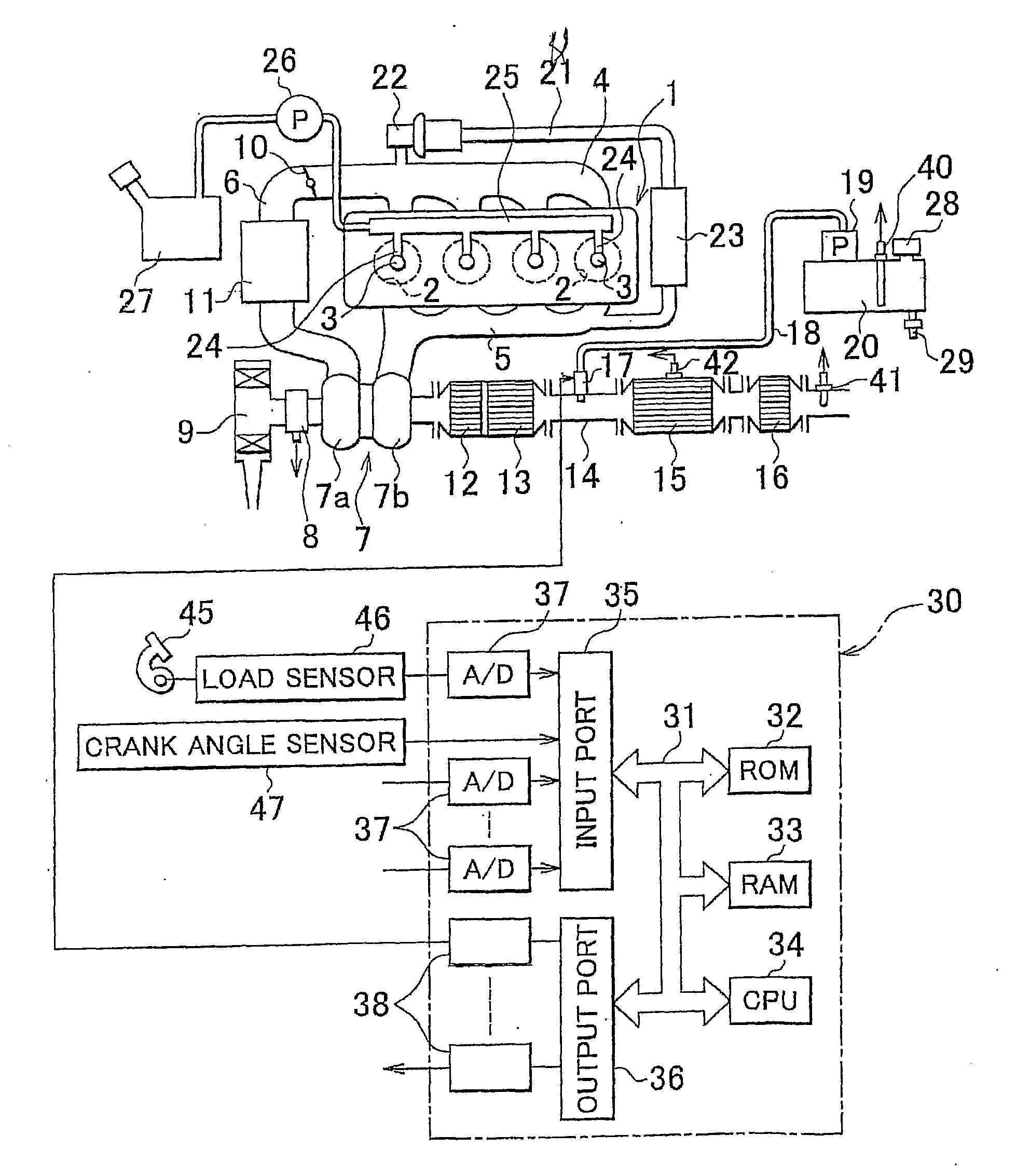
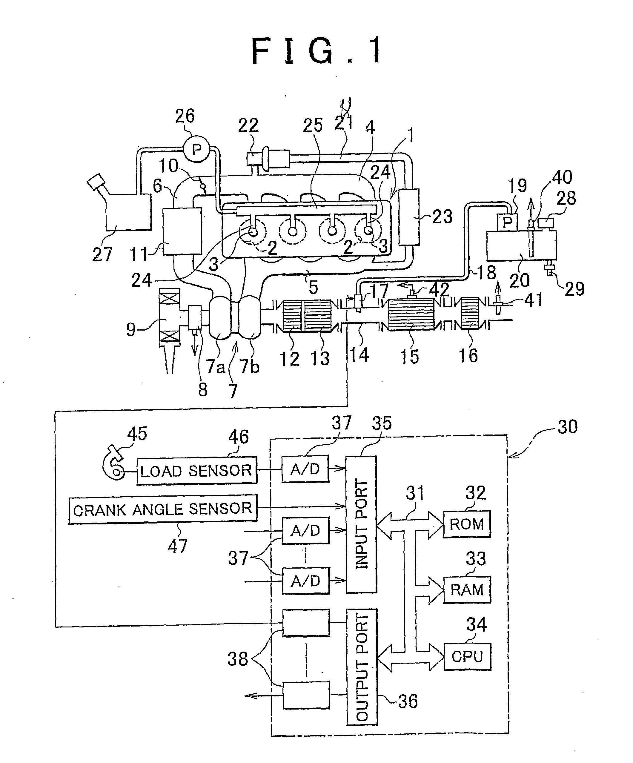
[0054]Thus, in the present invention as described below, it is determined by use of the level sensor 40 whether a supplementary liquid has been supplied into the aqueous-urea tank 20 for refilling. If it is determined that the supplementary liquid has been supplied into the aqueous-urea tank 20, and the NOx conversion efficiency detected after the supply of the supplementary liquid becomes lower than a predetermined permissible level, the concentration of aqueous urea in the aqueous-urea tank 20 is estimated from the detected NOx conversion efficiency.

[0055]In the second embodiment of the invention, if it is determined that the supplementary liquid has been supplied to the aqueous-urea tank 20, and the NOx conversion efficiency detected after the supply of the supplementary liquid is lower than the predetermined permissible level, an abnormal condition in which the concentration of aqueous urea in the aqueous-urea tank 20 is abnormally reduced is presumed to be established.

[0056]FIG...

third embodiment

[0065]In the third embodiment, assuming that the supplementary liquid added or supplied into the aqueous-urea tank 20 is a liquid whose ammonia concentration is equal to zero, the concentration of aqueous urea in the aqueous-urea tank 20 after the supply of the supplementary liquid is calculated based on the above assumption. The assumed concentration of aqueous urea is used for preventing the concentration of aqueous urea from being erroneously recognized as being reduced even though the concentration of aqueous urea is not actually reduced.

[0066]Supposing a Qa amount of supplementary liquid is supplied into the aqueous-urea tank 20 when a Qr amount of aqueous urea remains in the tank 20, as shown in FIG. 10A, the amount of aqueous urea in the aqueous-urea tank 20 increases from Qr to (Qr+Qa), as shown in FIG. 10B. Assuming that a supplementary liquid whose ammonia concentration is equal to zero is used as the supplementary liquid supplied to the aqueous-urea tank 20, which is a wo...

fourth embodiment

[0077]In the invention, therefore, a NOx conversion efficiency used for estimating the aqueous-urea concentration, which does not involve a reduction in the detected NOx conversion efficiency due to deterioration of the NOx sensor 41, is obtained from the detected NOx conversion efficiency detected by the NOx sensor 41, and a NOx conversion efficiency used for estimating the aqueous-urea concentration, which does not involve a reduction in the detected NOx conversion efficiency due to deterioration of the NOx selective reduction catalyst 15, is obtained from the detected NOx conversion efficiency detected by the NOx sensor 41, while a NOx conversion efficiency used for estimating the aqueous-urea concentration, which does not involve a reduction in the NOx conversion efficiency due to the defect of the aqueous-urea supply valve 17, is obtained from the detected NOx conversion efficiency detected by the NOx sensor 41. Then, the concentration of aqueous urea in the aqueous-urea tank 2...


PUM

PropertyMeasurementUnit
concentrationaaaaaaaaaa
liquid levelaaaaaaaaaa
RAaaaaaaaaaa

Abstract

In an exhaust emission control system of an internal combustion engine, a NOx selective reduction catalyst is disposed in an engine exhaust passage, and an aqueous solution of urea stored in an aqueous-urea tank is supplied to the NOx selective reduction catalyst so as to selectively reduce NOx. A NOx sensor is provided in the engine exhaust passage downstream of the NOx selective reduction catalyst for detecting the NOx conversion efficiency of the NOx selective reduction catalyst, and the concentration of aqueous urea in the aqueous-urea tank is estimated from the detected NOx conversion efficiency. The exhaust emission control system and method make it possible to detect the concentration of aqueous urea at reduced cost.

Description

BACKGROUND OF THE INVENTION[0001]1. Field of the Invention[0002]The invention relates to an exhaust emission control system of an internal combustion engine and its exhaust emission control method.[0003]2. Description of the Related Art[0004]In an exhaust emission control system of an internal combustion engine in which a NOx selective reduction catalyst is disposed in an engine exhaust passage, and an aqueous solution of urea stored in an aqueous-urea tank is supplied to the NOx selective reduction catalyst so that ammonia generated from aqueous urea selectively reduces NOx contained in exhaust gas, it is known in the art that an aqueous-urea concentration sensor is provided in the aqueous-urea tank for detecting an abnormality in the aqueous urea solution, as disclosed in, for example, Japanese Patent Application Publication No. 2005-83223 (JP-A-2005-83223).[0005]However, the aqueous-urea concentration sensor is expensive, and the use of another inexpensive method for detecting an...

Claims


Application Information

Patent Timeline
Patent Type & Authority Applications(United States)
IPC IPC(8): F01N11/00F01N3/10F02D45/00
CPCB01D53/90F01N13/009B01D53/9477B01D53/9495B01D2251/2062B01D2255/1021B01D2255/20707B01D2255/20723B01D2255/20738B01D2255/50F01N3/2066F01N2560/026F01N2560/06F01N2610/1453F01N2900/1621F01N2900/1806Y02T10/24F01N13/0097B01D53/9418F01N11/00F01N2550/05F01N2610/02F01N2900/1814Y02T10/12Y02T10/40
Inventor TOSHIOKA, SHUNSUKEODA, TOMIHISATANAI, YUTAKAASAURA, SHINYANAKAMURA, YOSHITAKA
Owner TOYOTA JIDOSHA KK
Why Eureka
Try Eureka