System for differential recovery of potential energy of boom of oil liquid hybrid power excavating machine

An oil-liquid mixing and recovery system technology, which is applied to mechanically driven excavators/dredgers, etc., can solve the problems of difficult to widely use potential energy recovery systems, large throttling loss of control valves, and expensive energy storage components, so as to save fuel. , Reduce the energy conversion link, the effect of strong portability

Inactive Publication Date: 2011-06-15
ZHEJIANG UNIV
View PDF7 Cites 37 Cited by
  • Summary
  • Abstract
  • Description
  • Claims
  • Application Information

AI Technical Summary

Problems solved by technology

The parallel hybrid hydraulic excavator systems of Komatsu and Hitachi use a separate hydraulic motor-generator to control the kinetic energy and potential energy of the boom lowering. The hydraulic motor of this system is connected in parallel in the oil circuit. When the boom is raised, the control valve exists. Large throttling loss
The above hybrid hydraulic excavator potential energy recovery system converts potential energy into electrical energy and stores it in the battery. There are many energy conversion links and energy storage components are expensive, which makes it difficult for this potential energy recovery system to be widely used.

Method used


Image

  • System for differential recovery of potential energy of boom of oil liquid hybrid power excavating machine
  • System for differential recovery of potential energy of boom of oil liquid hybrid power excavating machine
  • System for differential recovery of potential energy of boom of oil liquid hybrid power excavating machine

Examples


Embodiment Construction

[0017] The present invention will be further described below in conjunction with the accompanying drawings.

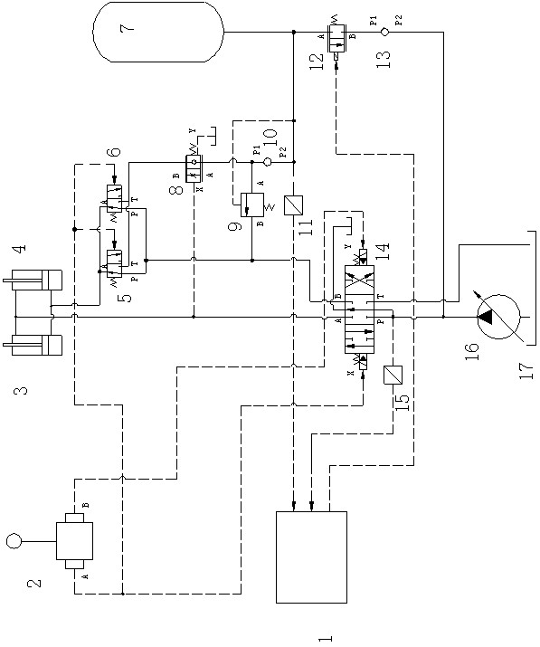
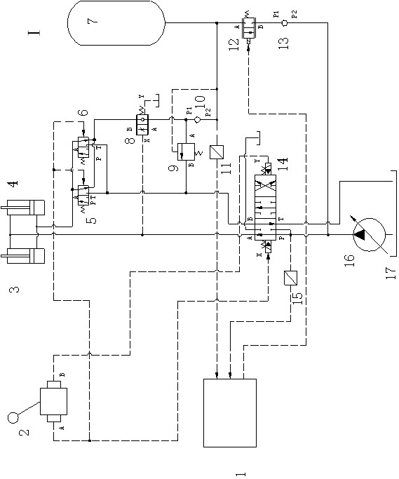
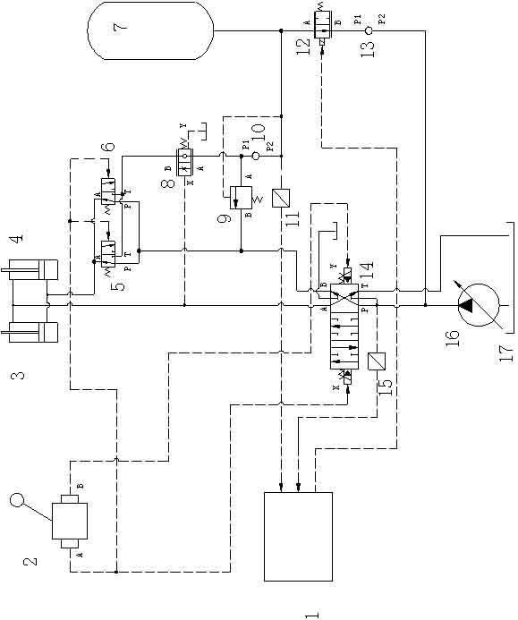
[0018] Such as figure 1 As shown, the oil-hydraulic hybrid excavator boom potential energy differential recovery system includes a controller 1, a pilot control handle 2, a boom hydraulic cylinder 3, a boom hydraulic cylinder 4, a two-position three-way hydraulic control reversing valve 5, two Three-way hydraulic control reversing valve 6, accumulator 7, directional throttle valve 8, hydraulic control overflow valve 9, one-way valve 10, pressure sensor 11, solenoid valve 12, one-way valve 13, multi-way valve 14 , pressure sensor 15, variable pump 16, fuel tank 17; the fuel tank 17 is connected with the variable pump 16, the variable pump 16 is connected with the P port of the multi-way valve 14, the T port of the multi-way valve 14 is connected with the fuel tank 17, the multi-way valve 14 The pilot control X port is connected to the A port of the pilot oil circuit co...


PUM


Abstract

The invention discloses a system for differential recovery of potential energy of a boom of an oil liquid hybrid power excavating machine. The system comprises a variable capacity pump, a multi-channel valve, a boom cylinder, an operating handle, a controller, a hydraulic control reversing valve, a hydraulic control reversing and throttling valve, a hydraulic control unloading valve, an energy accumulator, an electro-hydraulic proportional valve and a one-way valve. The controller is used for controlling the electro-hydraulic proportional valve and the variable capacity pump according to pressure at an outlet of the variable capacity pump and a pressure signal of the energy accumulator, thereby solving the flow distribution problem of the energy accumulator and the variable capacity pump. The energy accumulator is an energy storage element which can transform descending kinetic energy and potential energy of the boom to hydraulic energy and reasonably distribute the energy for a main power source and an auxiliary power source, and a working device is driven by the pump-energy accumulator. The system can avoid the waste of a large amount of the descending kinetic energy of the boom, reduce the energy transformation link, enable an engine to stably work in a high-efficient fuel oil region, improve the fuel coil economy of the excavating machine and reduce the emission of the system.

Description

technical field [0001] The invention relates to a potential energy recovery system, in particular to a potential energy differential recovery system for an oil-liquid hybrid excavator arm. Background technique [0002] Ordinary hydraulic excavators do not recycle the downward potential energy of the excavator arm, so that the downward potential energy of the boom is lost in the form of heat energy at the throttle port, which not only causes the system energy to be lost in vain, but also increases the temperature rise of the system, causing hydraulic pressure such as cavitation. System flaws. In addition, the working cycle of the excavator is relatively short and the frequency is high, so that the recyclable boom lowering potential energy is considerable. Therefore, the development of a set of potential energy recovery system for hydraulic excavator boom lowering can not only improve the hydraulic system of the excavator, but also save energy. [0003] At present, the energ...

Claims


Application Information

Patent Timeline
Patent Type & Authority Applications(China)
IPC IPC(8): E02F3/43
Inventor 管成林名润
Owner ZHEJIANG UNIV
Why Eureka
Try Eureka