[0013] Accordingly, it is an object of the present invention to provide a shield and an electronic apparatus having the same, which improves the economical efficiency of and
maintainability of the electronic apparatus, in which the above disadvantages are eliminated.
[0014] An electronic apparatus according to one aspect of the present invention includes a housing made of a first material, a functional member that is provided in the housing, is made of a second material, and has a predetermined function, and a shield that is made of the first material and hides the functional member, wherein the shield has an invisible perforation part in the shield, the perforation part being to be perforated by an external member in removing the shield from the housing. According to this electronic apparatus, the shield hides the functional member, and is removed when a sharp tool pierces through the perforation part, like a lid of milk
bottle. Since the perforation part is located inside the shield, the sharp tool does not damage the housing or require a replacement of the housing when the sharp tool perforates through the perforation part and removes the shield by leverage because the sharp tool uses the perimeter of the perforation part as a fulcrum instead of using the housing as a fulcrum. The easy removal of the shield improves the
operability. The invisible perforation part maintains the appearance continuity of the housing.
[0015] An electronic apparatus according to another aspect of the present invention includes a housing made of a first material, a functional member that is provided in the housing, is made of a second material, and has a predetermined function, and a shield that is removably provided to the housing, is made of the first material and hides the functional member, wherein the shield has no hole used to remove the shield from the housing. According to this electronic apparatus, the shield has no hole for removal, such as a perforation hole and a notch, lessens the likelihood of the disassembly and conversion of the housing, improving the safety. A removal of the shield may use a perforation of a sharp tool and other methods, such as use of a double-sided tape and a press button. Anyway, the housing does not get damaged in removing the shield, and the removal of the shield does not damage the housing or require a replacement of the housing.
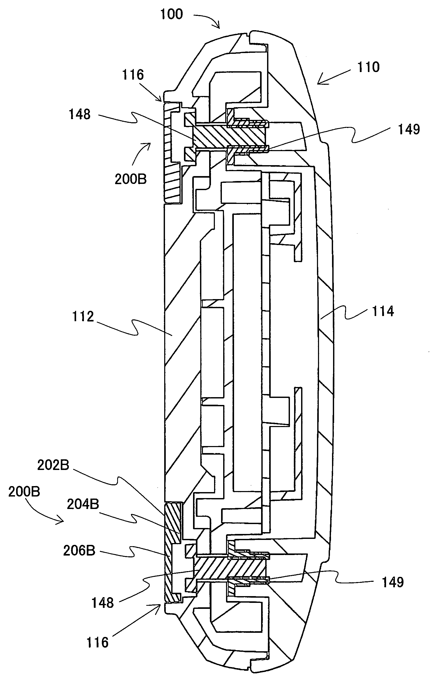
[0016] An electronic apparatus according to still another aspect of the present invention includes a housing made of a first material, a functional member that is provided in the housing, is made of a second material, and has a predetermined function, and a shield that is made of the first material and hides the functional member, wherein a fulcrum of a power applied in removing the shield from the housing is located inside the shield. This electronic apparatus arranges the fulcrum inside the shield, and definitely protects the housing from damages in comparison with the prior art that arranges the fulcrum at the boundary between the housing and the shield or outside the shield, such as on the housing.
[0017] The shield may have a sectionally concave shape at the perforation part, and is configured to be perforated at a concave of the perforation part. The shield may be made, for example, of resin, and a thickness of the perforation part is set, for example, to about 0.6 mm or smaller. A thin-walled structure of the perforation part facilitates the perforation by the sharp tool in removing the shield from the housing. The shield may have a symmetrical shape. Thereby, it is unnecessary to prepare plural types of shields in arranging the shields at left and right portions, improving the manufacturing performance and economical efficiency. The functional member is preferably located under the perforation part. For example, in removing the shield from the housing by piercing the sharp tool through the shield, the sharp tip is prevented from damaging the housing by inserting the sharp tool near the functional member, such as a screw.

