Automated warehouse

a warehouse and automatic technology, applied in the field of automatic warehouses, can solve the problems of increasing storage expenses, reducing the life of the chemical filter with increasing airflow, and affecting the operation of the clean gas supply unit, so as to achieve the effect of reducing the cleaning space, preventing the contamination of the article, and reducing the cost of maintenance and maintenan

Active Publication Date: 2014-02-27
MURATA MASCH LTD
View PDF19 Cites 1 Cited by
  • Summary
  • Abstract
  • Description
  • Claims
  • Application Information

AI Technical Summary

Benefits of technology

[0015]According to the above features, the transferring apparatus may rotate inside the first shield so that the opening for the holding space is exposed only when the apparatus transfers the article and closed when apparatus travels. Hence, the space to be cleaned is smaller, and contamination of the article is effectively prevented.
[0016]Moreover, the transferring apparatus may further be capable of vertically traveling inside the cylinder, and prior to the rotation inside the cylinder, the transferring apparatus may ascend or descend to a position where the opening for the holding space does not face either the first opening or the second opening. Such a feature prevents the opening from being exposed while the transferring apparatus is rotating.
[0017]Furthermore, the automated warehouse may include a second shield which is attached to an outer sidewall of the cylinder, travels together with the transferring apparatus and the first shield, and closes a loading and unloading opening on the storage rack to transfer the article when arriving at a position to face the storage rack. The second shield may include a connecting hole to selectively connect between the second opening on the first shield and a portion of the loading and unloading opening on the storage rack, the selective connection being made only to the portion through which the article passes. Such features make it possible to limit the area of the loading and unloading opening on the storage rack to a bare minimum, which contributes to more effective prevention of the contamination of the article.
[0018]Various preferred embodiments of the present invention allow a holding space alone to be kept clean instead of the entire transportation route of articles. Hence, the space that is to be kept clean is much smaller and contamination of the articles is successfully prevented.

Problems solved by technology

Here, a chemical filter for the clean gas supply unit is a very expensive and expendable, and the life of the chemical filter decreases with an increasing amount of airflow.
In other words, in the case where the clean gas is to be supplied to all the above spaces, the chemical filter will have to be replaced in a short period of time and the resulting expenses for the storage will increase.

Method used


Image

  • Automated warehouse
  • Automated warehouse
  • Automated warehouse

Examples


embodiment 1

Preferred Embodiment 1

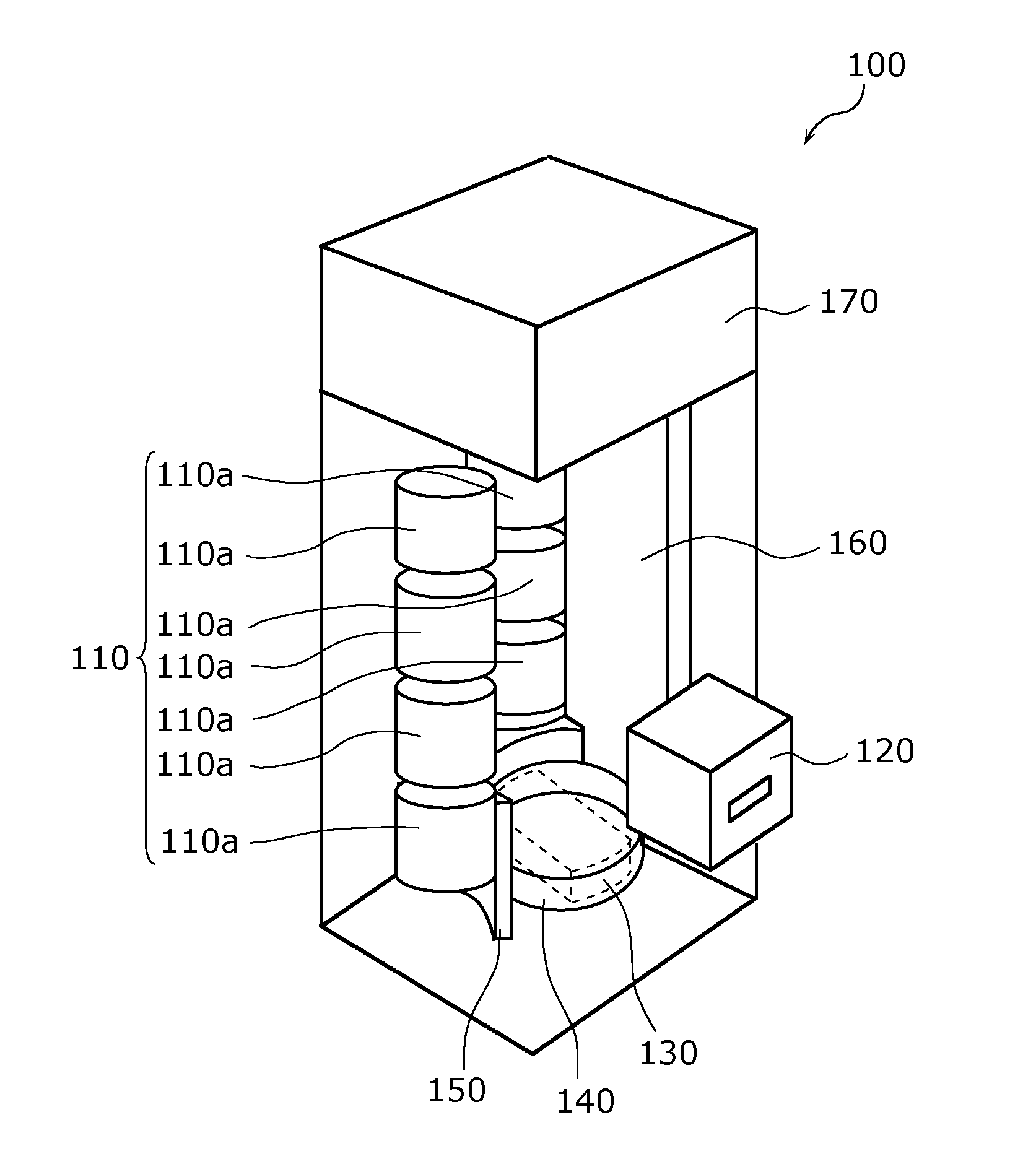
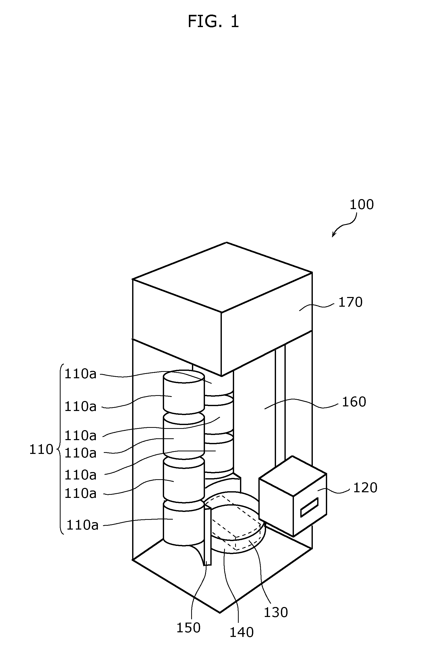
[0036]FIG. 1 schematically shows a clean stocker 100 which exemplifies an automated warehouse according to Preferred Embodiment 1 of the present invention. As shown in FIG. 1, the clean stocker 100 mainly includes a storage rack 110, a load port 120, a transferring apparatus 130, a first shield 140, a second shield 150, an elevator guide 160, and a cleaning unit (fan filter unit or FFU) 170. The clean stocker 100 is preferably installed in a clean room of a semiconductor factory or a liquid crystal display factory, and separately stores reticles (articles) for exposure for either semiconductors or liquid crystal substrates, and pods (cases) for containing the reticles.

[0037]The storage rack 110 stores a reticle taken out of a pod. The structure of the storage rack 110 shall not be defined in particular. As the example in FIG. 1 shows, the storage rack 110 preferably includes multiple reticle chambers 110a. More specifically, the reticle chambers 110a are vertic...

embodiment 2

Preferred Embodiment 2

[0066]FIG. 12 schematically shows the clean stocker 100 which exemplifies an automated warehouse according to Preferred Embodiment 2 of the present invention. It is noted that the details shared between Preferred Embodiments 1 and 2 shall be omitted, and mainly described here are the differences therebetween.

[0067]In the clean stocker 100 shown in FIG. 12, the load port 120 travels together with the transferring apparatus 130. Moreover, the loading and unloading space 121 of the load port 120 and the holding space 131 of the transferring apparatus 130 are connected with each other. Furthermore, the first shield 140 covers all the load port 120 and the transferring apparatus 130 to close the loading and unloading space 121 and the holding space 131 that are connected with each other. The cleaning unit 170 (not shown in FIG. 12) then supplies the interconnected loading and unloading space 121 and holding space 131 with CDA to keep the spaces clean.

[0068]The above...


PUM


Abstract

A clean stocker includes a storage rack storing an article, a load port holding a case and including a loading and unloading space to load and unload the article to and from the held case, a transferring apparatus including a holding space to hold the article and transfer the article between the holding space and the storage rack and between the holding space and the case held in the loading and unloading space, the holding space being kept clean, and a first shield closing the holding space and traveling together with the transferring apparatus.

Description

BACKGROUND OF THE INVENTION[0001]1. Field of the Invention[0002]The present invention relates to automated warehouses and, in particular, to an automated warehouse which stores articles in a clean space.[0003]2. Description of the Related Art[0004]Reticles have been used for manufacturing electronic components, and are stored in a clean stocker placed in a clean room (See Japanese Unexamined Patent Application Publication No. 2008-30914, for example). In the clean stocker, the reticles are taken out of pods for storage, and the environment inside the clean stocker chassis needs to be kept from volatile impurities.[0005]A clean stocker disclosed in Japanese Unexamined Patent Application Publication No. 2008-30914 is equipped with a clean gas supply unit, placed in the upper part of the chassis of the clean stocker, to supply clean gas in order to prevent the volatile impurities from entering the chassis.[0006]The above conventional structure, however, requires the clean gas to be sup...

Claims


Application Information

Patent Timeline
Patent Type & Authority Applications(United States)
IPC IPC(8): H01L21/677
CPCH01L21/67769H01L21/67772H01L21/67775
Inventor GAMBE, MASAHIKO
Owner MURATA MASCH LTD
Why Eureka
Try Eureka