Actuator device, multi-shaft driving device, and robot device

a technology of multi-shaft driving and actuator device, which is applied in the direction of arms, manufacturing tools, and gears, can solve the problems of deteriorating the output density of the actuator device and the mounting density of the parts, increasing the possibility of interference with the surroundings, and causing the finger to be caught in the vicinity, etc., to achieve high output density and mounting density.

Active Publication Date: 2014-03-06
SONY CORP
View PDF9 Cites 28 Cited by
  • Summary
  • Abstract
  • Description
  • Claims
  • Application Information

AI Technical Summary

Benefits of technology

[0051]According to the technology disclosed in the present specification, it is possible to provide the excellent actuator device, multi-shaft driving device, and robot device, which may be used in a plurality of sites of the multi-shaft driving mechanism such as the multi-shaft manipulator, the robot arm, the leg structure, and the snake-shaped robot.
[0052]Also, according to the technology disclosed in the present specification, it is possible to provide the excellent actuator device, multi-shaft driving device, and robot device capable of maintaining the high output density and mounting density without the large substantial occupied space even when they are used in a plurality of sites of the multi-shaft driving mechanism.
[0053]Still another object, feature, and advantage of the technology disclosed in the present specification will become clear by more detailed description with reference to an embodiment to be described later and the attached drawings.

Problems solved by technology

When the substantial occupied space of the actuator becomes large, possibility of interference with the surroundings increases correspondingly and a risk that user's finger, wiring and the like get caught therein arises.
However, a structure body covered with the exterior has a wasted space (vacuum or containing only air) not for an original object of the actuator (parts, torque generation, torque conversion and the like) in the driving mechanism, so that output density of the actuator device and mounting density of the parts are deteriorated.
As a result, this makes a multi-joint robot formed of the actuator devices used in a plurality of sites large and limits a range in which an entire multi-joint robot may move and an operable range thereof, or reduces a range of motion of each joint.

Method used


Image

  • Actuator device, multi-shaft driving device, and robot device
  • Actuator device, multi-shaft driving device, and robot device
  • Actuator device, multi-shaft driving device, and robot device

Examples


Embodiment Construction

[0079]An embodiment of the technology disclosed in the present specification is hereinafter described in detail with reference to the drawings.

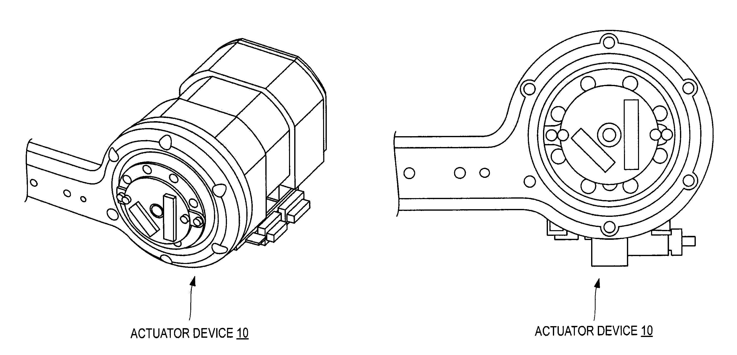
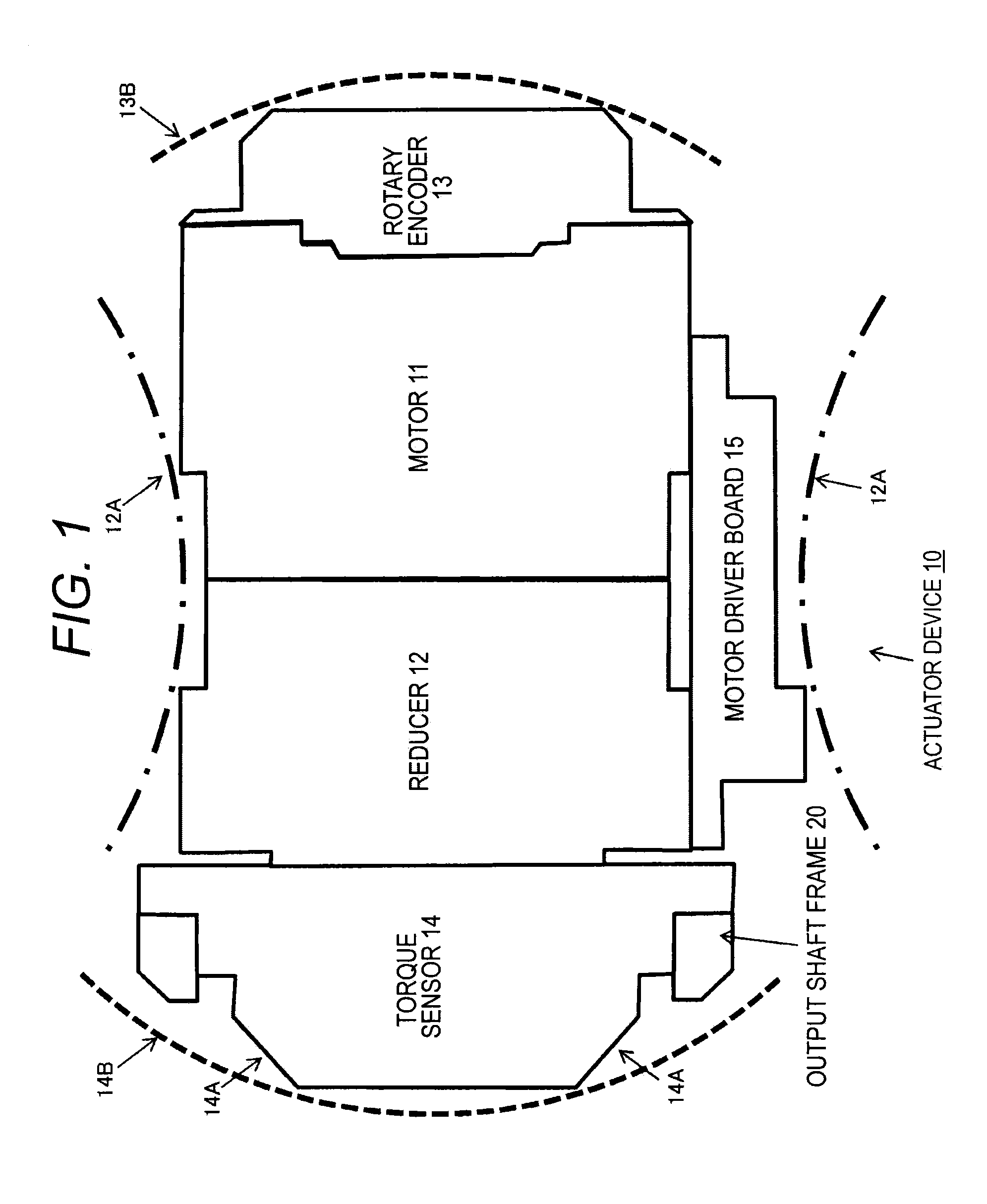
[0080]FIG. 1 schematically illustrates a configuration of an actuator device 10 according to one embodiment of the technology disclosed in the present specification. The illustrated actuator device 10 is provided with a motor 11, a reducer 12, a rotary encoder 13, a torque sensor 14, and a motor driver board 15.

[0081]The motor 11 is a brushless motor, for example. An entire length in an output shaft direction of an entire actuator device 10 is preferably made short in view of reducing an occupied area thereof when this is used as an actuator on a subsequent stage rotated by an actuator on a preceding stage in a multi-shaft driving mechanism. A large-diameter motor is used for reducing the entire length while maintaining an output of the motor 11. A wave reduction gear such as a harmonic drive (TM) may be used, for example, as the reducer 12.

[...


PUM


Abstract

Provided is an actuator device used in a plurality of sites of a multi-shaft driving mechanism such as a multi-shaft manipulator, a robot arm, a leg structure and a snake-shaped robot.
A torque sensor 14 is connected to a bearing 17 such as a cross roller bearing through a mount part. As illustrated, the torque sensor 14 is driven by an outer ring relative to a stationary part case 19 of an actuator device 10. An attachment surface of an output shaft frame 20 is arranged in a position offset from the bearing 17 on a side of the stationary part case 19. An entire length of the actuator device 10 in an output shaft direction does not change also after the output shaft frame 20 is attached and an occupied space does not increase.

Description

TECHNICAL FIELD[0001]The technology disclosed in the present specification relates to an actuator device, a multi-shaft driving device, and a robot device used in a multi-shaft driving mechanism such as a multi-shaft manipulator, a robot arm, a leg structure, and a snake-shaped robot, and especially relates to the actuator device, the multi-shaft driving device, and the robot device used in a plurality of sites of the multi-shaft driving mechanism.BACKGROUND ART[0002]The actuator device is formed of an actuator motor alone or is modularized with a peripheral circuit, wiring, a connector, an attachment frame and the like. It is possible to realize a simple mechanism, a reduced cost, reduction in types of parts, and improved maintainability by using the same actuator devices in a plurality of sites in the multi-shaft driving mechanism such as the multi-shaft manipulator, the robot arm, the leg structure, and the snake-shaped robot. For example, a manipulator of an industrial robot for...

Claims


Application Information

Patent Timeline
Patent Type & Authority Applications(United States)
IPC IPC(8): B25J9/02F16H21/40
CPCB25J9/02Y10S901/23F16H21/40B25J9/06B25J9/126B25J13/085B25J9/08H02K7/116H02K11/215H02K11/24Y10T74/18568Y10T74/20317
Inventor TANAKA, AKICHIKA
Owner SONY CORP
Why Eureka
Try Eureka