Culinary slicer

Active Publication Date: 2014-03-06
KAI R&D CENT CO LTD
View PDF2 Cites 10 Cited by
  • Summary
  • Abstract
  • Description
  • Claims
  • Application Information

AI Technical Summary

Benefits of technology

[0021]An adjustment member for moving the first receiving part is movably mounted in a slicer frame; a means for moving the adjustment member is a worm provided on a drive part; and further, a deflection mechanism is present between the adjustment member and the first receiving part, for converting the motion of the adjustment member into motion that changes the height of the first receiving part with respect to the slicing blade, the deflection mechanism comprising inclined faces provided on the first receiving part and the adjustment member, which are inclined in the vertical direction, the inclined faces facing each other and being able to slide on each other. By virtue of this configuration, the adjustment member is moved by way of turning the worm by operating a drive part, and the movement of the adjustment member is converted into a movement that changes the height of the first receiving part with respect to the slicing blade, whereby the thickness of the sliced food can be adjusted.
[0022]The deflection mechanism is a deflection mechanism combining: a deflection mechanism comprising inclined faces provided on the first receiving part and the adjustment member, which are inclined in the vertical direction, the inclined faces facing each other and being able to slide on each other; and a deflection mechanism wherein an inclined groove, which is inclined in the vertical direction, is formed on either one of the first receiving part or the adjustment member, and an engagement part that engages in the inclined groove is provided on the other of the first receiving member and the adjustment member. If a configuration is adopted fo

Problems solved by technology

This slicer is not provided with a securing means to prevent the movable adjustment body from being moved downward as a result of the pressure exerted by food during use.
This is because, since the angle of inclination of the two facing inclined faces is small, the force that acts in the direction that would cause the two inclined faces to slide when subjected to pressure from the food is not great enough to overcome the fric

Method used


Image

  • Culinary slicer
  • Culinary slicer
  • Culinary slicer

Examples


Example

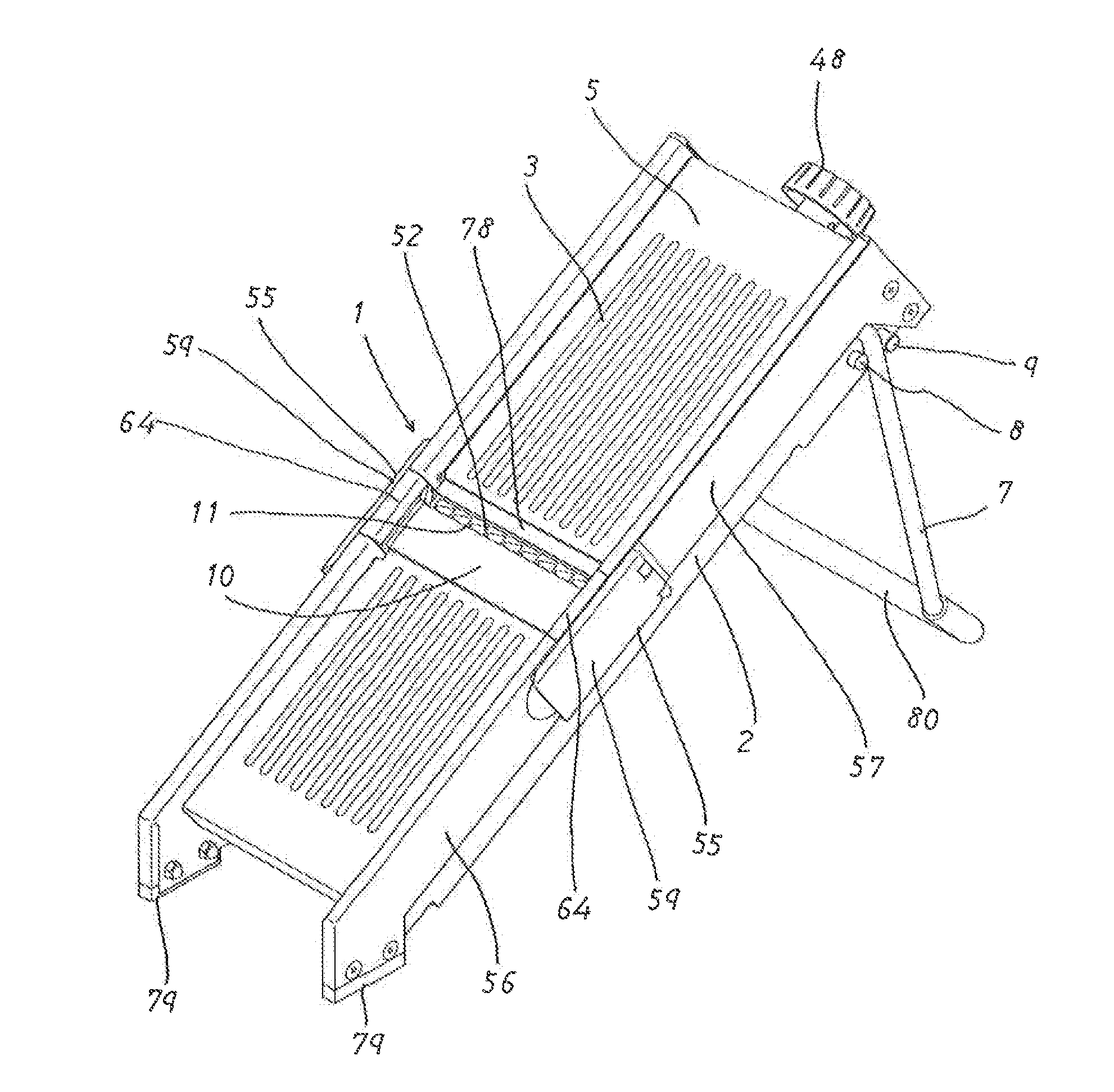
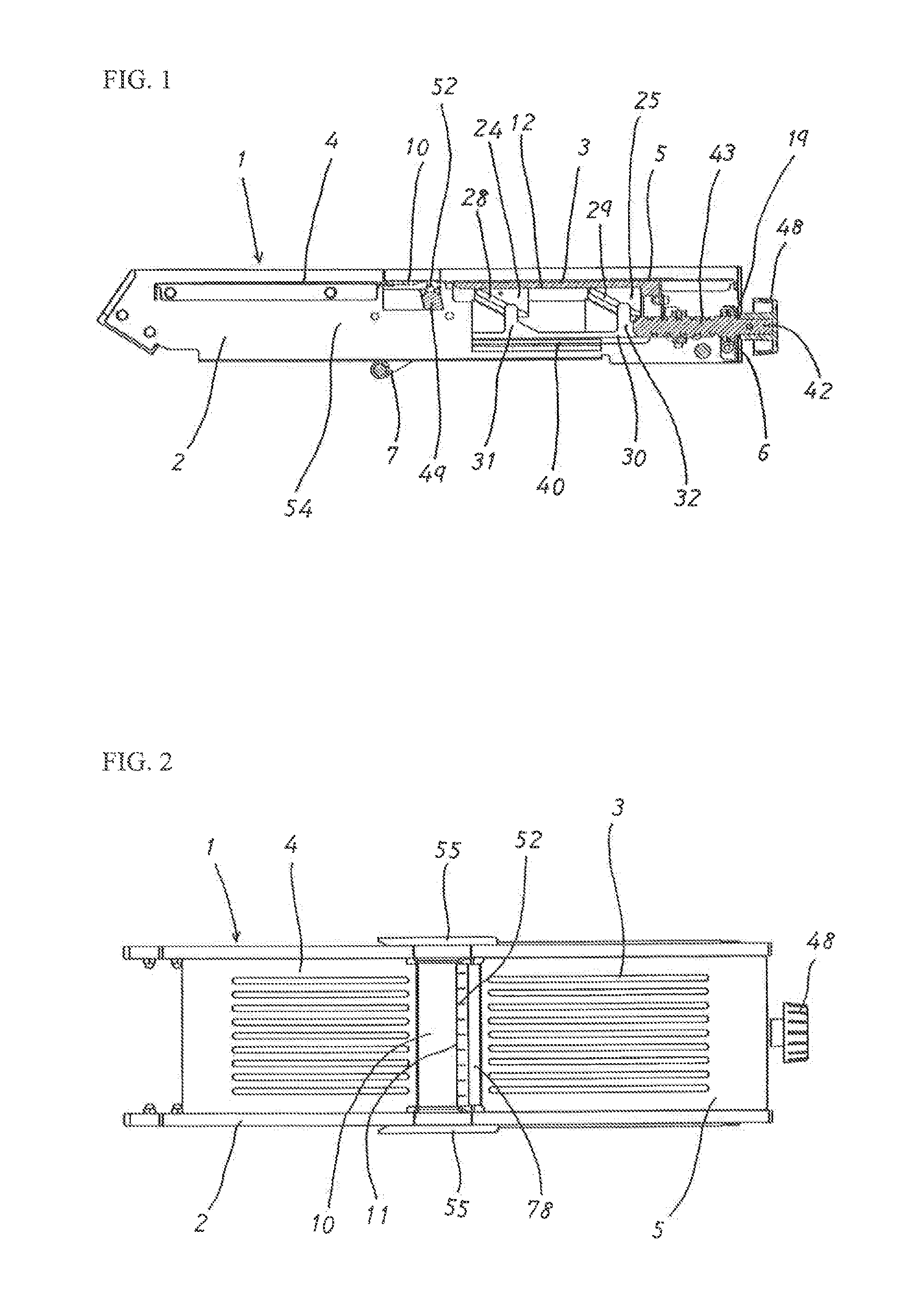
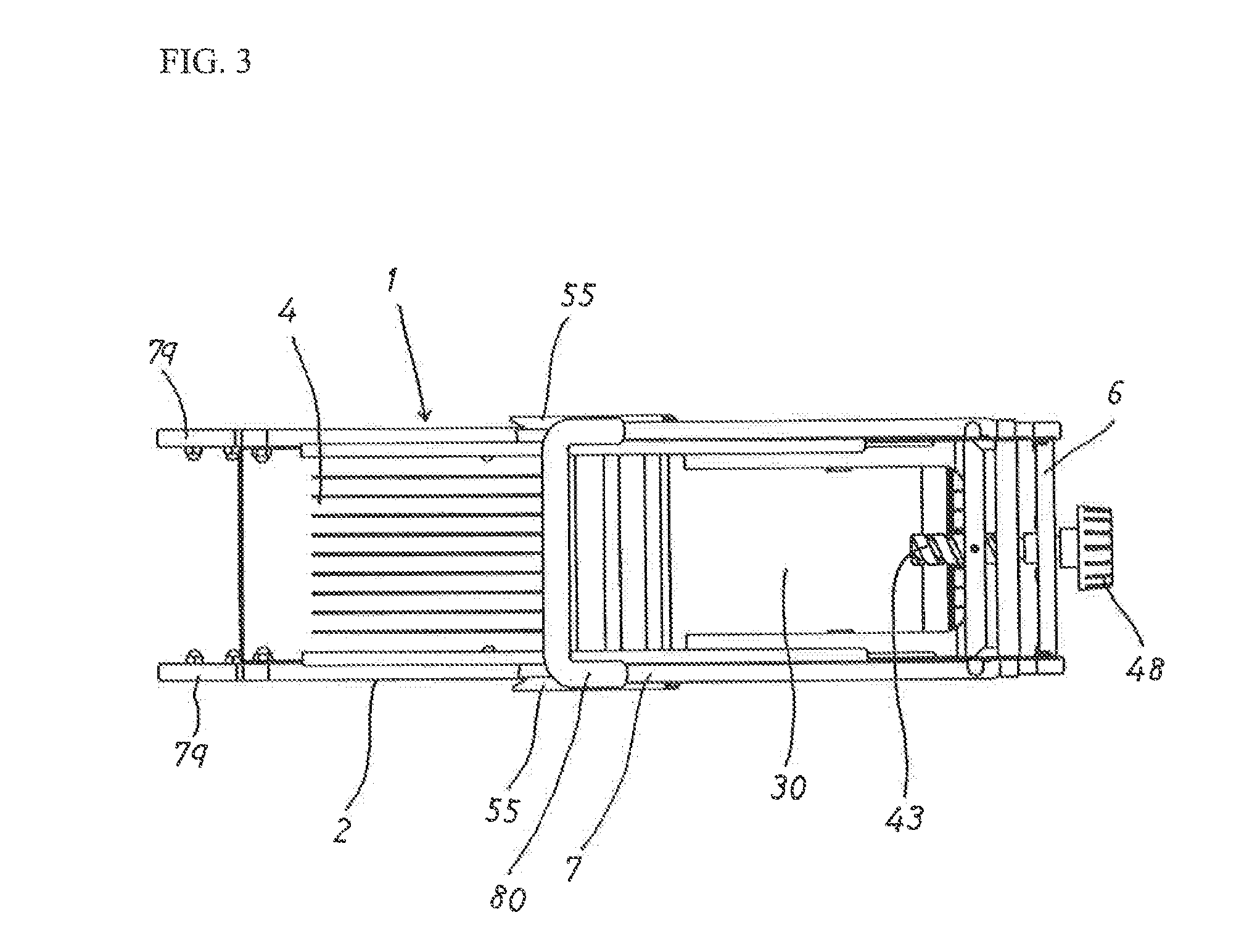
[0039]Embodiments of the present invention will be described. As shown in FIG. 1, the slicer 1 of the present invention comprises a frame 2, a first receiving part 3 and a second receiving part 4. The frame 2 and the second receiving part 4 are made from stainless steel sheets. The first receiving part 3 comprises a base member 12 made from plastic and a top plate 5 made from a stainless steel sheet. The first receiving part 3 is capable of perpendicular translation in the vertical direction, which allows the thickness of the sliced food to be adjusted. The second receiving part 4 is secured to the frame 2.

[0040]As shown in FIG. 4, a stand 7 is turnably mounted on the frame 2, and is kept closed when not in use by way of engagement on an engagement protrusion 8. As shown in FIG. 5, when in use, the stand 7 is opened by way of turning it and, with this maintained at a prescribed angle of opening by way of a stopper 9, the slicer 1 can be used in an inclined state. Furthermore, contac...


PUM

PropertyMeasurementUnit
Thicknessaaaaaaaaaa
Heightaaaaaaaaaa

Abstract

A slicer with which the thickness of sliced food can be varied includes a movable receiving part that receives sliding food and is subjected to downward pressure from the food, the movable receiving part not moving downward due to the pressure even if a means for securing the receiving part in place is not separately provided. An adjustment member for moving a vertically mobile first receiving part is mounted in a frame of the slicer so as to be forwardly and rearwardly movable. A means for moving the adjustment member is a worm that is provided on a drive shaft. A deflection mechanism is present between the adjustment member and the first receiving part which converts the forward and rearward motion of the adjustment member into vertical motion of the first receiving part.

Description

TECHNICAL FIELD[0001]The present invention relates to a culinary slicer that can be used for household purposes or for professional purposes, and which allows the thickness of the food that is sliced to be adjusted.BACKGROUND OF THE INVENTION[0002]Culinary slicers are configured so that, by sliding food forward from the top face of a first receiving part to the top face of a second receiving part, the food is sliced by a slicing blade that is mounted at the boundary between the first receiving part and the second receiving part. Next, in order to adjust the thickness of the food that is sliced, a configuration is adopted in which, for example, the first receiving part is movably mounted, and the height of the first receiving part is changed with respect to the slicing blade. In the slicer in Patent Document 1, in order to make the first receiving part movable, a bottom inclined face of a movable sliding plate, which is the first receiving part, and the inclined face of an adjustment...

Claims


Application Information

Patent Timeline
IPC IPC(8): B26D1/08
CPCB26D1/08B26D3/283B26D2003/286Y10T83/9478
Inventor KOIDE, TAKASHI
Owner KAI R&D CENT CO LTD
Why Eureka
Try Eureka