
Conveying arrangement for processing printed products

a technology for conveying arrangements and printed products, applied in the direction of drying, pile separation, lighting and heating apparatus, etc., can solve the problems of affecting the further affecting the processing of printed products, and affecting the processing efficiency of printed products

Active Publication Date: 2006-07-11
MULLER MARTINI HLDG
View PDF18 Cites 7 Cited by
  • Summary
  • Abstract
  • Description
  • Claims
  • Application Information

AI Technical Summary

Benefits of technology

[0007]It is an object of the invention to create a conveying arrangement that avoids the previously mentioned disadvantages.
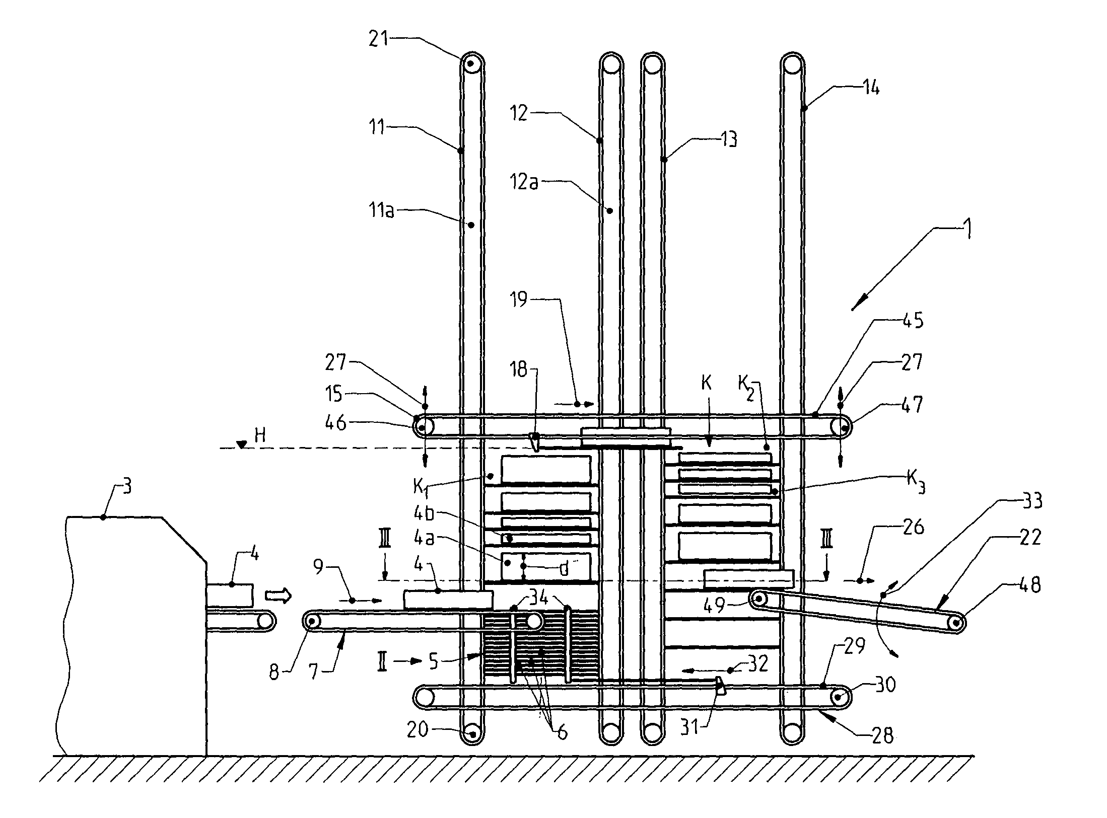
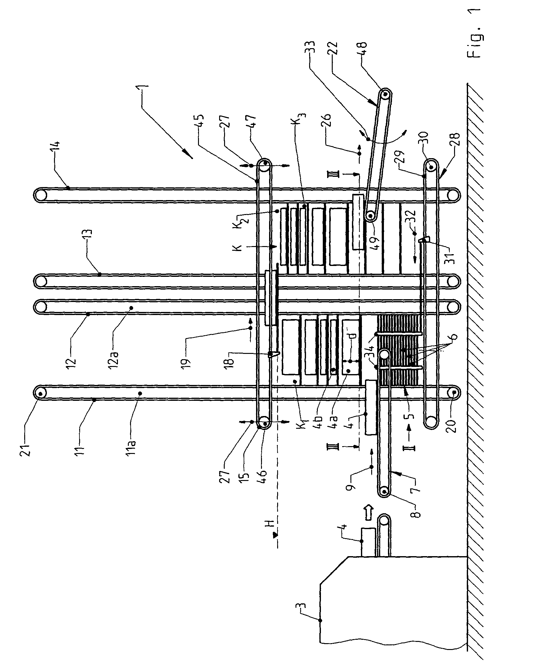
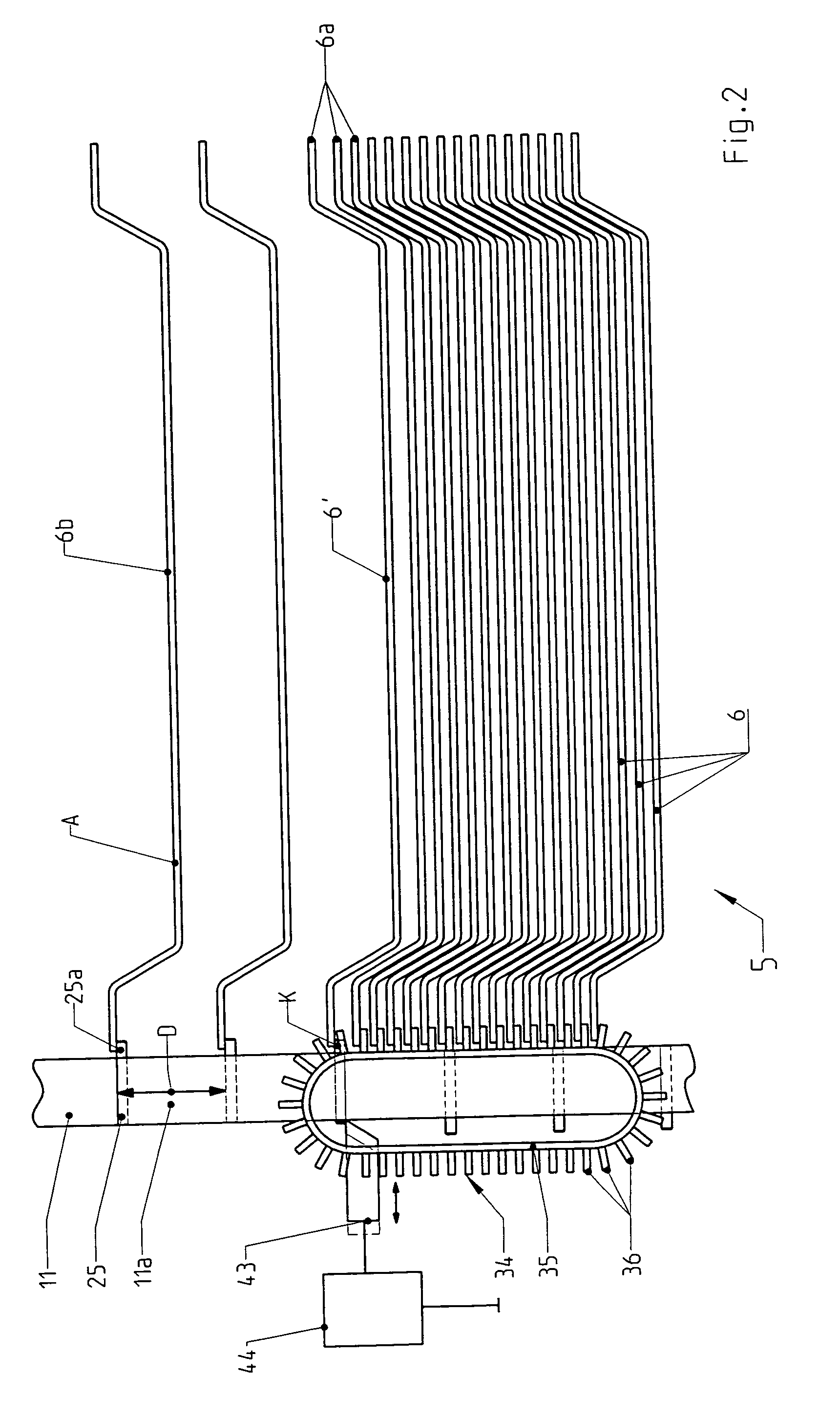
[0011]With a conveying arrangement according to the invention, the spacing between the deposit trays can be adjusted to adapt to the respective thickness of the printed products. The conveying arrangement can be designed to operate precisely at the maximum printing capacity, such that it never operates over capacity or under capacity despite the printed products having different thickness and / or different formats. The thickness and format differences of printed products can optionally change within a row of successive printed products, which is particularly advantageous for a so-called “finishing on demand” operation, where different types of printed products are generated successively with a digital printer while the printer is operating at a constant printing capacity. With the conveying arrangement according to the invention, a constant conveying time and / or a constant cooling time, in the case of a cooling section, can be achieved with a constant printing capacity using the same conveying section, wherein the format and thickness of a product can vary. In the case of a cooling section, printed products of different thicknesses can be cured during the same optimum cooling time.
[0012]According to one exemplary embodiment of the invention, the spacing is respectively adjusted by inserting a deposit tray from a deposit tray magazine located below the conveying section into the conveying section. This results in a particularly cost-effective and operationally safe design. According to a second exemplary embodiment of the invention, the deposit trays are respectively removed from a deposit tray magazine located at an end of the conveying section. In both exemplary embodiments, a displacement device can be used to push the deposit trays from the magazine and make them available for conveyance along the conveying section. According to the second exemplary embodiment of the invention, the deposit trays are transported with a lifting device to the conveying section, wherein the desired spacing is adjusted in the process.

Problems solved by technology

This is a comparatively space-saving design, but is disadvantageous in that much machine timing between different processing sections is lost and interferes with the further processing of the printed products.
The disadvantage of this design is that, for a fast-running perfect binder, an extremely high tower of several meters in height, is required to gain the required cooling time.
Such changes are undesirable in many cases.

Method used


Image

  • Conveying arrangement for processing printed products
  • Conveying arrangement for processing printed products
  • Conveying arrangement for processing printed products

Examples


Embodiment Construction

[0021]FIG. 1 depicts a conveying arrangement 1 having an intake area 7 for supplying printed products 4 to a conveying section K in the direction of an arrow 9. The printed products 4, for example, are perfect bound books and magazines which are taken over from, for example, a perfect binder 3, which can be any conventionally known perfect binder. Alternatively, the printed products 4, can be loose sheet stacks, thread-stitched stacks or brochures, and the perfect binder 3 can be replaced by any appropriate binder or paper feeder for supplying the respective printed products 4. In a digital printer, stacks of sheets for the printed products 4 can be printed with a commonly known “on-demand” technique, and digital printing machines may vary considerably from one to another, especially, with respect to the thickness of printed products. Thick printed products 4a and thin printed products 4b are depicted in FIG. 1, wherein any sequence of the thick and thin printed products 4a–b can be...


PUM

PropertyMeasurementUnit
Thicknessaaaaaaaaaa
Areaaaaaaaaaaa
Distanceaaaaaaaaaa

Abstract

A conveying arrangement for processing printed products, comprising a conveying section, a plurality of deposit trays on which the printed products are transported along the conveying section, the conveying section having an intake area where the printed products are fed to the deposit trays and a delivery area at an end region of the conveying section where the printed products are removed from the deposit trays, and a control mechanism for controlling a distance between respectively adjacent deposit trays in the intake area based on a thickness of the printed products.

Description

CROSS-REFERENCE TO RELATED APPLICATION[0001]This application claims the priority of European Patent Application Serial No. 2405801.8-1256, filed on Sep. 13, 2002, the subject matter of which is incorporated herein by reference.BACKGROUND OF THE INVENTION[0002]The invention relates to a conveying arrangement for processing printed products. The arrangement has an intake area where the printed products are fed to a conveying section, a plurality of deposit trays on which the printed products are transported along the conveying path and a delivery area at the end of the conveying path where the printed products are conveyed off.[0003]During the processing, the printed products can be transported from one processing station to another with conveying arrangements of the aforementioned type. The printed products can be any type including, for example, perfect bound or thread-stitched book blocks, loose book stacks, loose sheets or brochures. In the processing stations, the printed product...

Claims


Application Information

Patent Timeline
IPC IPC(8): B65G43/00B65G47/51B65H29/16B65H9/00B65H33/16F26B15/10F26B25/00
CPCB65G47/5131F26B15/10F26B25/003B65H2301/42256B65H2301/4312B65H2511/13B65H2511/22B65H2220/01B65H2220/02B65H2220/11
Inventor LANGENEGGER, DANIELSCHNEEBERGER, HANSJORG
Owner MULLER MARTINI HLDG
Learn More