Thrust bearing and suspension for vehicle

a technology for thrust bearings and vehicles, applied in the direction of elastic bearings, bearing units, shock absorbers, etc., can solve the problem of lightening the weight of caps, and achieve the effect of simple design and easy manufacturing

Active Publication Date: 2014-10-07
AB SKF
View PDF10 Cites 8 Cited by
  • Summary
  • Abstract
  • Description
  • Claims
  • Application Information

AI Technical Summary

Benefits of technology

[0010]More particularly, the object of the present invention is to provide an economic suspension thrust bearing device of simple design that is easy to manufacture and is lightweight.
[0012]Producing the insert in synthetic material makes it possible to have great flexibility in its production and makes it easy to vary its thickness if necessary. Moreover, it lightens the weight of the cap relative to a cap comprising a metal reinforcing insert. Moreover, the manufacture of such a cap is simplified and relatively fast. After use, the cap can also be recycled more easily.
[0013]In one embodiment, the synthetic material of the insert is rigid and the synthetic material of the body is more flexible. The insert thus forms a reinforcing or stiffening insert or framework making it possible to reinforce the mechanical strength of the cap against the forces exerted by the suspension spring. It is possible to provide the insert with zones of variable thickness depending on the intensity of the forces to be withstood.
[0014]Alternatively, the synthetic material of the insert is flexible and the synthetic material of the body is more rigid. In this case, the synthetic material of the body makes it possible to withstand and transmit the forces exerted by the suspension spring, the insert made of a more flexible and cheaper material making it possible to reduce the overall cost of the cap. The insert forms a filler framework for the body of the cap so as to obtain a low-cost cap.

Problems solved by technology

Moreover, it lightens the weight of the cap relative to a cap comprising a metal reinforcing insert.

Method used


Image

  • Thrust bearing and suspension for vehicle
  • Thrust bearing and suspension for vehicle
  • Thrust bearing and suspension for vehicle

Examples


Embodiment Construction

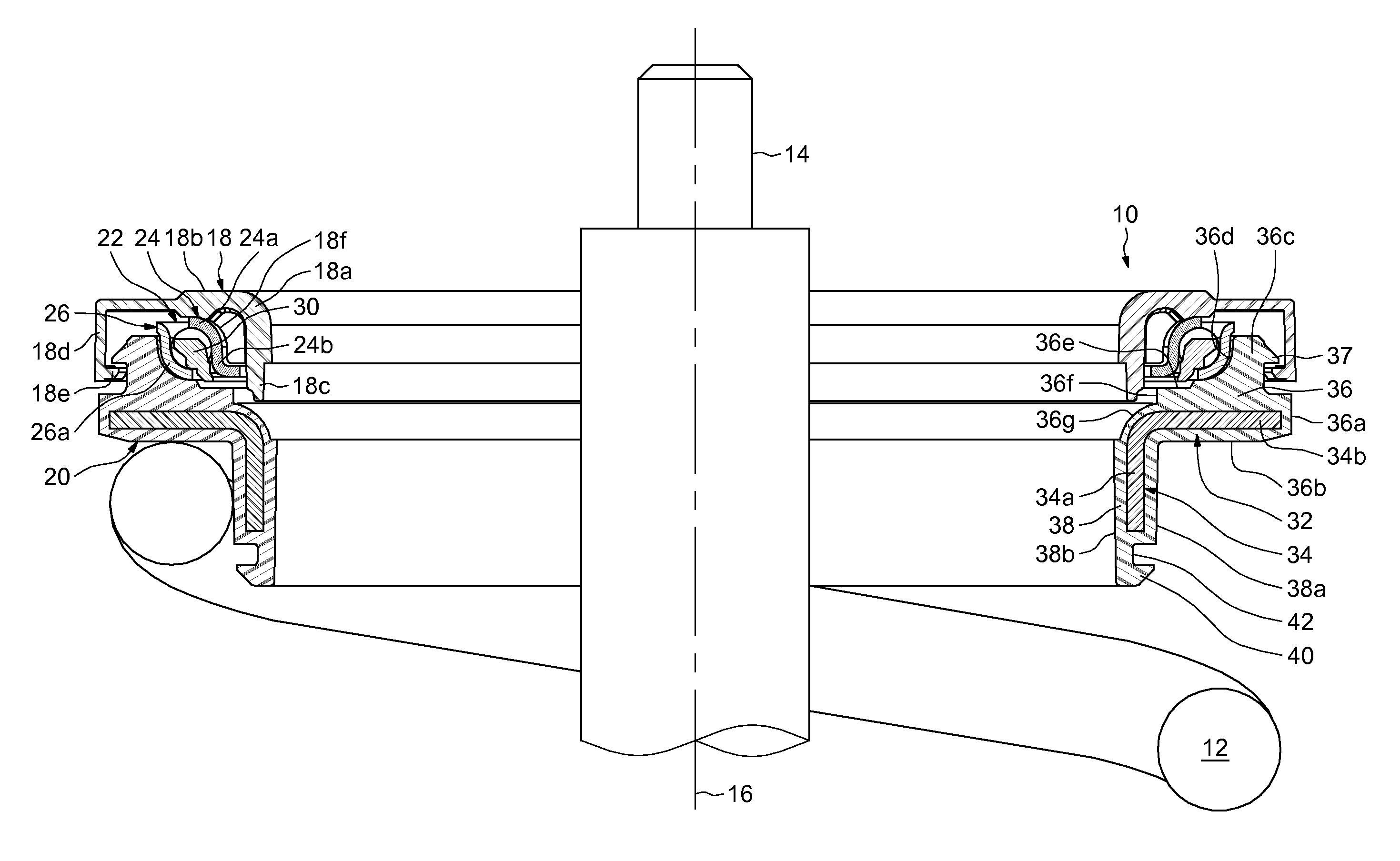
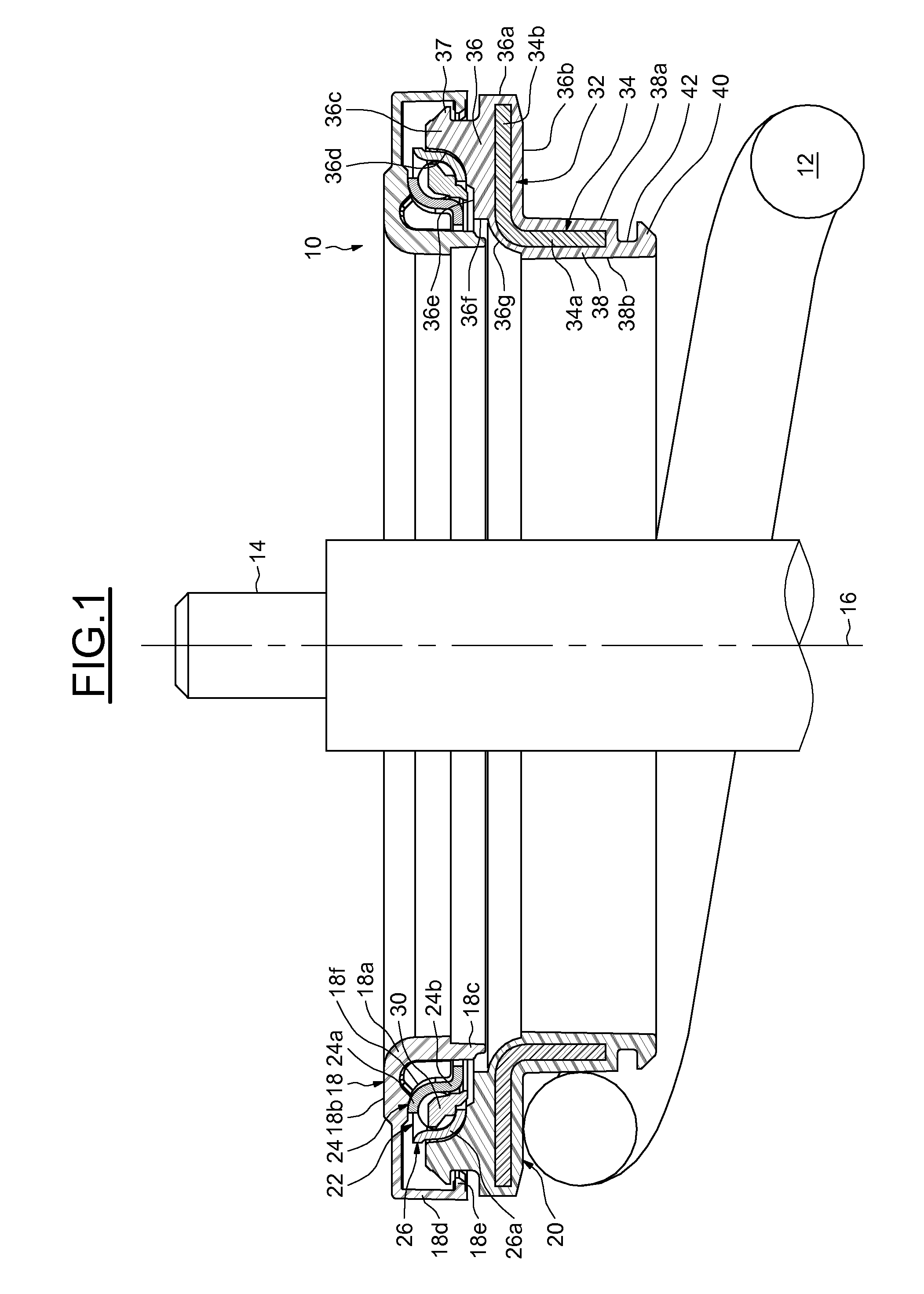
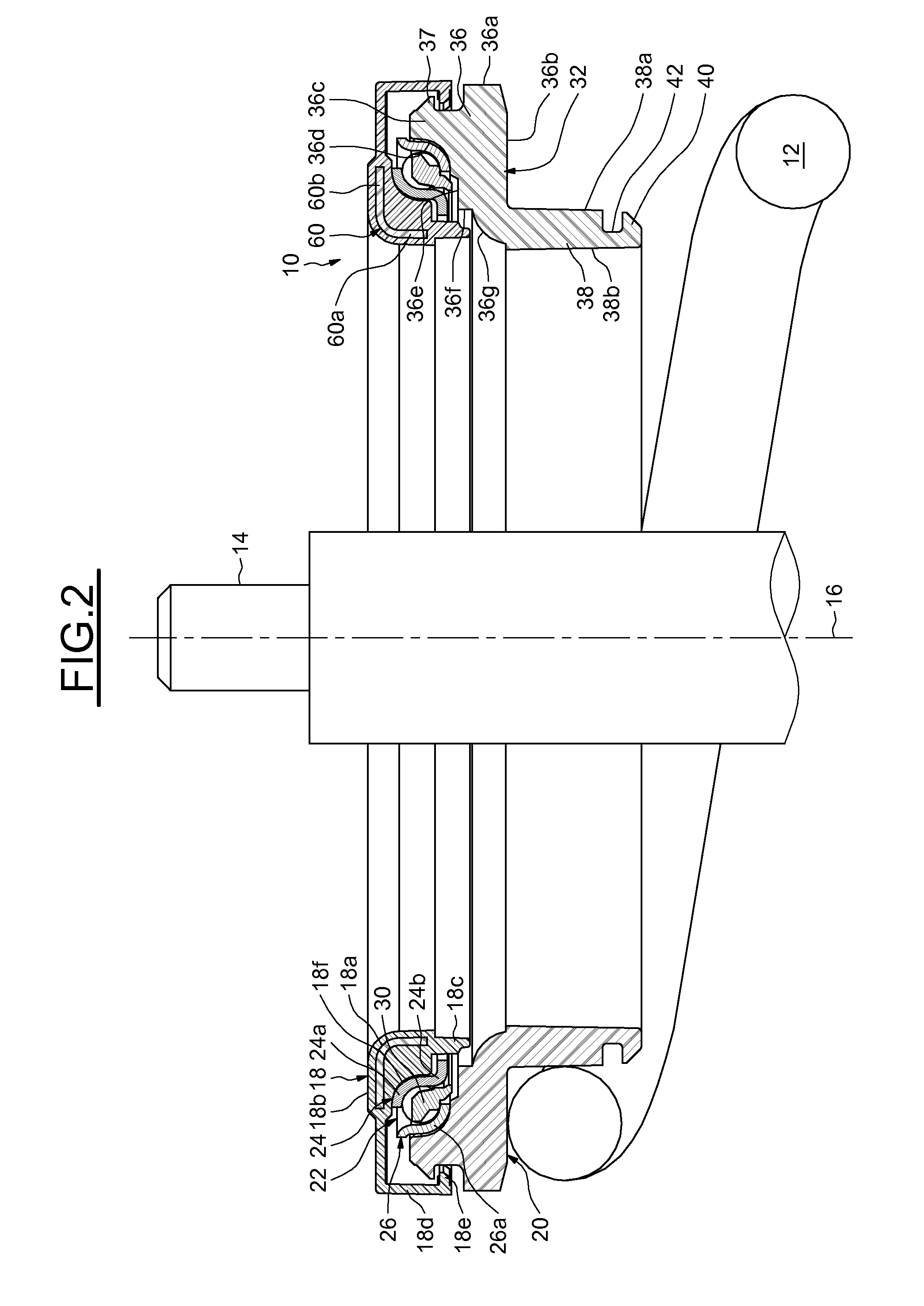
[0022]FIG. 1 shows a suspension thrust bearing device, indicated by the general reference number 10, designed to be mounted between an element of the chassis of a motor vehicle and a suspension spring 12 of the helical type. The device 10 is placed around a damper rod 14, the axis 16 of which is considered to be vertical, the said rod being axially elongate in the form of a cylinder of revolution. The suspension spring 12 is mounted around the damper rod 14.

[0023]The device 10, with its axis 16, comprises an upper bearing cap 18 designed to rest against a filtering elastic block interposed between the device and the chassis of the vehicle, a lower supporting cap 20 forming a bearing means for the suspension spring 12, and a rolling bearing 22 placed axially between the said caps and forming an axial thrust.

[0024]The bearing cap 18 may consist in a one-piece body made by moulding of a synthetic material, for example a polyamide. It comprises an annular solid portion 18a the upper rad...


PUM

PropertyMeasurementUnit
flexibleaaaaaaaaaa
radial forcesaaaaaaaaaa
axial forcesaaaaaaaaaa

Abstract

The suspension thrust bearing device for a motor vehicle comprises a rolling bearing (22) forming a thrust and provided with an upper ring, a lower ring, and at least one row of rolling elements placed between the rings, a bearing cap (18) in contact with the upper ring, and a supporting cap (20) in contact with the lower ring and forming a bearing means for a suspension spring (12). At least one of the said caps comprises a body formed of at least a first synthetic material and an insert (34) at least partly covered by the said body. The said insert is formed of at least a second synthetic material different from the first synthetic material.

Description

CROSS-REFERENCE[0001]This application is the US national stage of International Application No. PCT / EP2010 / 069655 filed on Dec. 14, 2010, which claims priority to French Application No. FR 0959536 filed Dec. 23, 2009.FIELD OF THE INVENTION[0002]The present invention relates to the field of suspension thrust bearing devices used in particular in motor vehicles in the suspension struts of the steered wheels.BACKGROUND OF THE INVENTION[0003]Such a suspension thrust bearing device usually comprises a rolling bearing forming an axial thrust and comprising an upper ring and a lower ring between which a plurality of rolling elements are placed, for example balls or rollers. Preferably, a rolling bearing with oblique contact is used making it possible to absorb both the radial forces and the axial forces exerted on the device. The upper and lower rings are usually mounted in contact with upper and lower bearing or support parts such as dishes or caps. The upper and lower caps form a housing...

Claims


Application Information

Patent Timeline
Patent Type & Authority Patents(United States)
IPC IPC(8): F16C19/10B60G15/06F16C27/06F16C27/08
CPCB60G15/068F16C27/08F16C27/066B60G2204/418F16C19/10F16C2326/05B29C45/14F16C19/16F16F9/36F16F9/54B60G13/00B60G15/02B60G15/06B60G2206/013
Inventor CORBETT, RICHARDHOUDAYER, CHRISTOPHEVIAULT, SAMUEL
Owner AB SKF
Why Eureka
Try Eureka