Stabilized high flow doctor blade head for transfer roller

a transfer roller and stabilizer technology, applied in the field of stabilizer blade head transfer rollers, can solve the problems of large starvation spots (dropouts) on anilox rollers, and achieve the effects of high velocity, lower overall fluid pressure, and high fluid flow ra

Inactive Publication Date: 2014-03-06
HARRIS & BRUNO MACHINE
View PDF4 Cites 7 Cited by
  • Summary
  • Abstract
  • Description
  • Claims
  • Application Information

AI Technical Summary

Benefits of technology

[0011]The present invention generally comprises an improved doctor blade head for coating a transfer roller. The doctor blade head is provided with several salient features that enable a high velocity flow of coating liquid longitudinally through the doctor blade chamber, while requirin

Problems solved by technology

They also keep the chamber cavity completely filled at all times of operation, not allowing air into the cav

Method used


Image

  • Stabilized high flow doctor blade head for transfer roller
  • Stabilized high flow doctor blade head for transfer roller
  • Stabilized high flow doctor blade head for transfer roller

Examples


Embodiment Construction

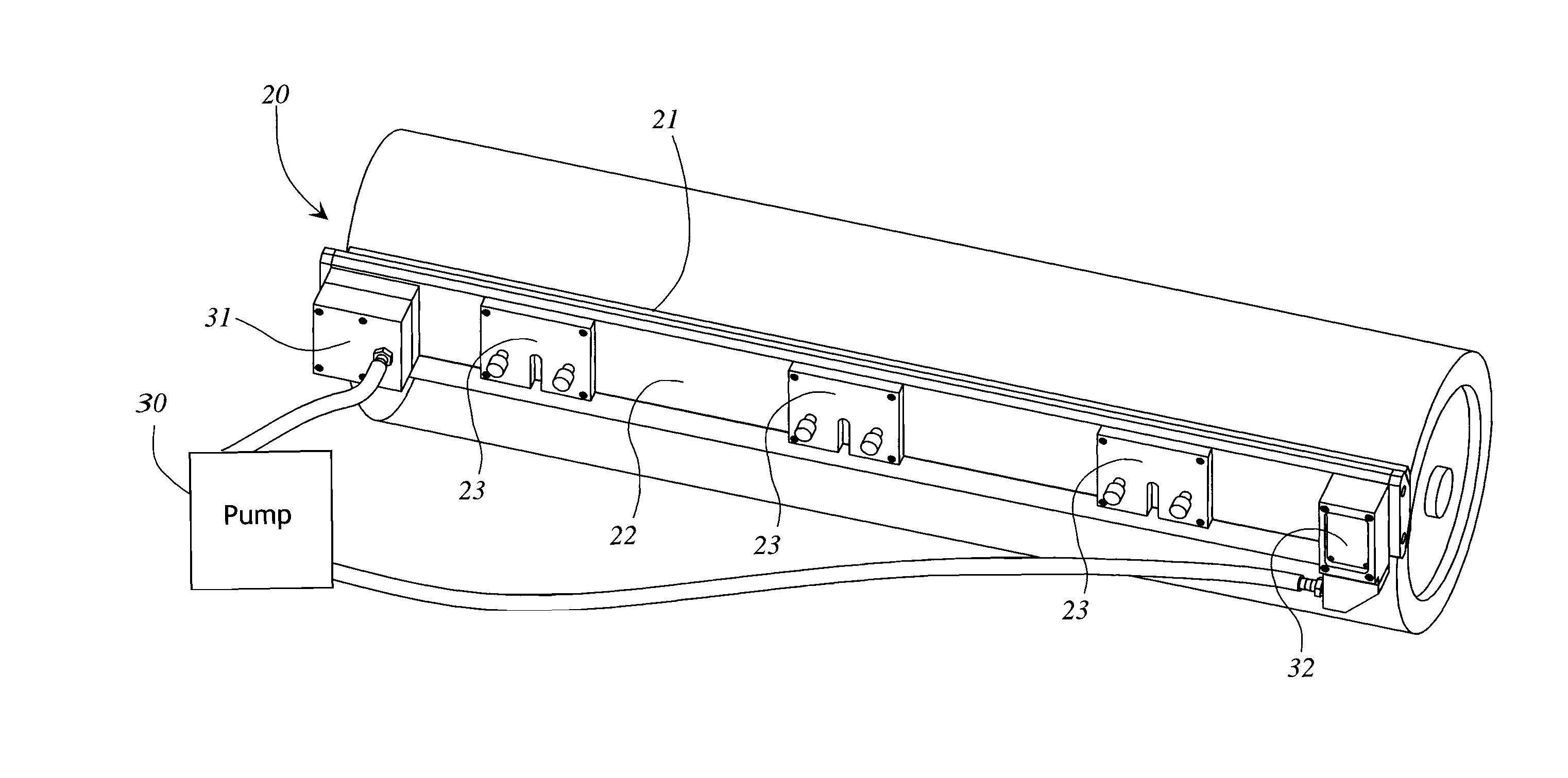
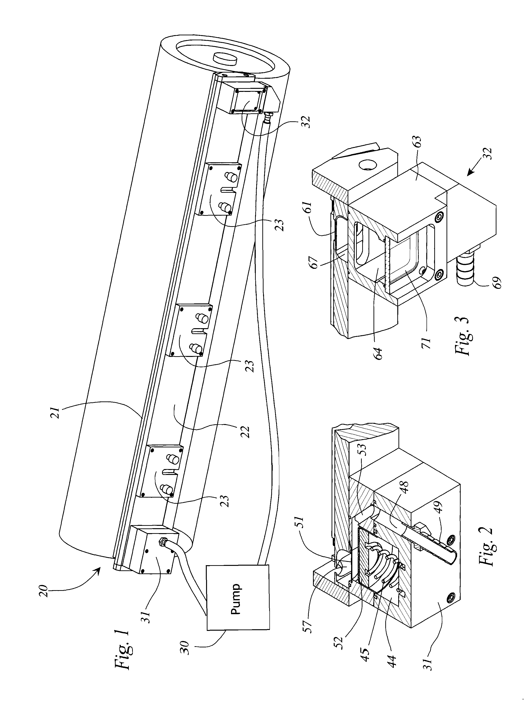
[0022]The present invention generally comprises an improved doctor blade head for coating a transfer roller that delivers a high velocity flow of coating liquid longitudinally through the doctor blade chamber, while providing a lower, more stable fluid pressure across the chamber. As shown in FIG. 1, the doctor blade head 20 generally includes a channel-like structure 21 having a central web portion 22 with a plurality of mounting brackets 23 for securing the doctor blade head to a supporting framework (not shown). The head 20 includes a longitudinally extending cavity 24 (FIG. 10B) that has a longitudinally extending opening 26. A pair of doctor blades 27 are secured in opposed, parallel fashion adjacent to the opening 26, and are disposed to impinge on a rotating transfer roller 28, whereby a film of coating fluid is applied to the roller. The roller may comprise an anilox roller or the equivalent known in the prior art.

[0023]As shown in FIG. 1, a fluid pump 30 has its output conn...


PUM


Abstract

A doctor blade head for coating a transfer roller includes a semi-cylindrical cavity to enable streamline fluid flow therethrough, and check plates at the inlet and outlet openings for permitting unidirectional flow into the inlet opening from said pump and out of the outlet opening toward the pump. An hydraulic accumulator acts as a fluid pressure and fluid velocity balancing device, and includes a rolling diaphragm piston moving in a cylinder that is connected to the inlet fluid path, with a spring impinging on the piston to absorb pressure surges and compensate pressure dropoffs.

Description

CROSS-REFERENCE TO RELATED APPLICATIONS[0001]Not Applicable.FEDERALLY SPONSORED RESEARCH[0002]Not applicable.SEQUENCE LISTING, ETC ON CD[0003]Not applicable.BACKGROUND OF THE INVENTION[0004]1. Field of the Invention[0005]This invention relates to doctor blade systems for applying coatings in a printing or coating process, and in particular to a new design for the doctor blade head.[0006]2. Description of Related Art[0007]In the application of liquid substances to a moving web or successive sheets of material, it is considered well known in the art to apply the liquid using a rotating transfer roller, and to directly apply the liquid uniformly onto the roller by means of a doctor blade assembly. The doctor blade assembly generally includes a reservoir chamber extending the length of the transfer roller and in contact with the circumferential surface thereof, and a pair of doctor blades extending longitudinally on either side of the chamber. The doctor blades are angled obliquely towa...

Claims


Application Information

Patent Timeline
IPC IPC(8): B05C11/04
CPCB05C1/0834B05C11/042B05C11/045B05C11/047B05C11/048D21H23/22B05C11/04B41F31/027B05C1/0817B05C1/0813
Inventor RIGA, JR., THOMAS JAMESFIEGUTH, AARON STEPHENGUBBELS, DANNY RICHARD
Owner HARRIS & BRUNO MACHINE
Why Eureka
Try Eureka