Crystal growing device

Inactive Publication Date: 2014-03-06
C SUN MFG
View PDF3 Cites 0 Cited by
  • Summary
  • Abstract
  • Description
  • Claims
  • Application Information

AI Technical Summary

Benefits of technology

[0019]The effect of the present invention resides in that the heat transmitting block absorbs heat evenly from the platform, and the heat exchanger takes away heat from the heat transmitting block, so as to keep

Problems solved by technology

Such uneven surface of the crystal 98 is und

Method used


Image

  • Crystal growing device
  • Crystal growing device
  • Crystal growing device

Examples


Embodiment Construction

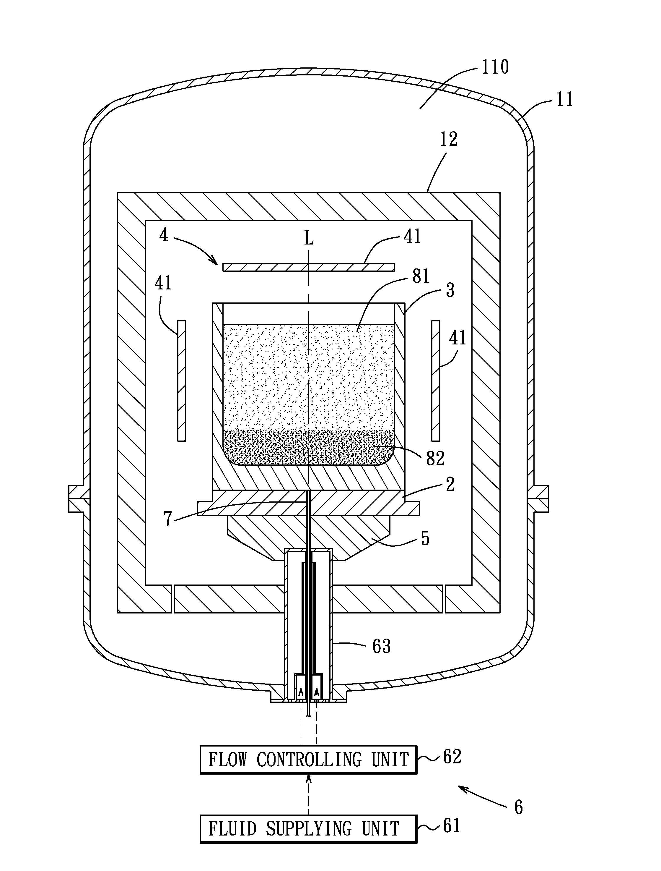
[0026]As shown in FIGS. 3 and 4, a crystal growing device of a preferred embodiment according to the present invention is provided for a crystal growing process. The crystal growing device includes a furnace 11, a cage 12, a platform 2, a crucible 3 with an axis (L), a heating unit 4, a heat transmitting block 5, a heat exchanger 6, and a temperature sensor 7.

[0027]The furnace 11 defines a chamber 110 therein. The platform 2 is disposed in the chamber 110 and has a top surface 21 and a bottom surface 22. The platform 2 is made of a material with high thermal conductivity in this preferred embodiment and defines a first channel 201 therein along the axis (L).

[0028]The crucible 3 is disposed in the chamber 110 and on the top surface 21 of the platform 2 for receiving a crystal seed layer 82 and a raw material 81 therein. The crucible 3 has a bottom wall 31 and a surrounding wall 32 extending upwardly from a periphery of the bottom wall 31. The crystal seed layer 82 is disposed on an i...


PUM


Abstract

A crystal growing device includes a furnace, a platform, a crucible, a heating unit, a heat transmitting block, and a heat exchanger. The furnace defines a chamber therein. The platform is disposed in the chamber and has a top surface and a bottom surface. The crucible is disposed on the top surface of the platform for receiving a crystal seed layer and a raw material therein. The heating unit is disposed in the chamber and surrounds the crucible. The heat transmitting block is disposed at the bottom surface of the platform and is made of a material with high thermal conductivity. The heat exchanger is coupled to the heat transmitting block for absorbing heat from the heat transmitting block.

Description

CROSS-REFERENCE TO RELATED APPLICATION[0001]This application claims priority of Taiwanese Application No. 101217002, filed on Sep. 4, 2012.BACKGROUND OF THE INVENTION[0002]1. Field of the Invention[0003]This invention relates to a crystal growing device, more particularly to a crystal growing device including a heat exchanger.[0004]2. Description of the Related Art[0005]Referring to FIG. 1, a conventional crystal growing device 900 is shown to include a platform 95, a crucible 92 disposed on the platform 95 for receiving a crystal seed layer 94 and a silicon material 93, and a plurality of heaters 91 disposed around the crucible 92. A crystal growing process may include the following stages: heating, melting, crystallizing, annealing, and cooling. When the crystal growing device 900 is utilized, the silicon material 93 is heated by the heaters 91 at the heating stage and melted completely at the melting stage. At the crystallizing stage, the molten raw material 93 starts to crystall...

Claims


Application Information

Patent Timeline
IPC IPC(8): C30B11/00
CPCC30B11/003
Inventor YU, JEN-PINCHANG, CHEN-WEIHSIEH, CHIA-YING
Owner C SUN MFG
Why Eureka
Try Eureka