Method for laser welding metal workpieces using a combination of weld paths

a technology of laser welding and metal workpieces, applied in the direction of laser beam welding apparatus, welding/soldering/cutting articles, manufacturing tools, etc., to achieve the effect of slowing down the cooling ra

Active Publication Date: 2022-11-08
GM GLOBAL TECH OPERATIONS LLC
View PDF147 Cites 0 Cited by
  • Summary
  • Abstract
  • Description
  • Claims
  • Application Information

AI Technical Summary

Benefits of technology

[0013]The method may include the additional step of advancing the laser beam along a third weld path, which overlaps with each of the first weld path and the second weld path, to provide the laser weld joint with a top surface having a surface roughness (Ra) of 15 μm or less. In that regard, the laser beam may be advanced along the third weld path, without a keyhole being present, while the elongated melt puddle is still in a molten state so that the laser beam impinges an upper surface of the elongated melt puddle and introduces heat into an upper region of the elongated melt puddle to slow the rate of cooling of the upper surface of the elongated melt puddle so that, upon solidification, the top surface of the laser weld joint is rendered smooth. Or, as another option, the laser beam may be advanced along the third weld path after the elongated melt puddle has fully solidified into the laser weld joint so that the laser beam impinges the top surface of the laser weld joint and momentarily remelts a top region of the laser weld joint so that, upon resolidification, the top surface of the laser weld joint is rendered smooth.

Problems solved by technology

The practice of laser welding can present challenges for certain types of metal workpieces.
Thus, when a steel workpiece that includes a zinc-based surface coating is laser welded, high-pressure zinc vapors are readily produced at the surfaces of the steel workpiece and have a tendency to disrupt the laser welding process.
When an adequate escape outlet is not provided, zinc vapors may remain trapped in the molten workpiece metal as it cools and solidifies, which may lead to defects in the resulting weld joint—such as entrained porosity—as well as other weld joint discrepancies such as spatter, blowholes, and undercut joints.
These weld joint deficiencies, if sever enough, can unsatisfactorily degrade the mechanical properties of the laser weld joint.
But the formation of these protruding features adds an additional step to the overall laser welding process and is believed to contribute to the occurrence of undercut weld joints.
Because the surface oxide coating is difficult to break down and is a poor conductor of heat, it can suppress the rate of heat transfer into the underlying bulk aluminum or magnesium, at least at the outset of the laser welding process.

Method used


Image

  • Method for laser welding metal workpieces using a combination of weld paths
  • Method for laser welding metal workpieces using a combination of weld paths
  • Method for laser welding metal workpieces using a combination of weld paths

Examples


Embodiment Construction

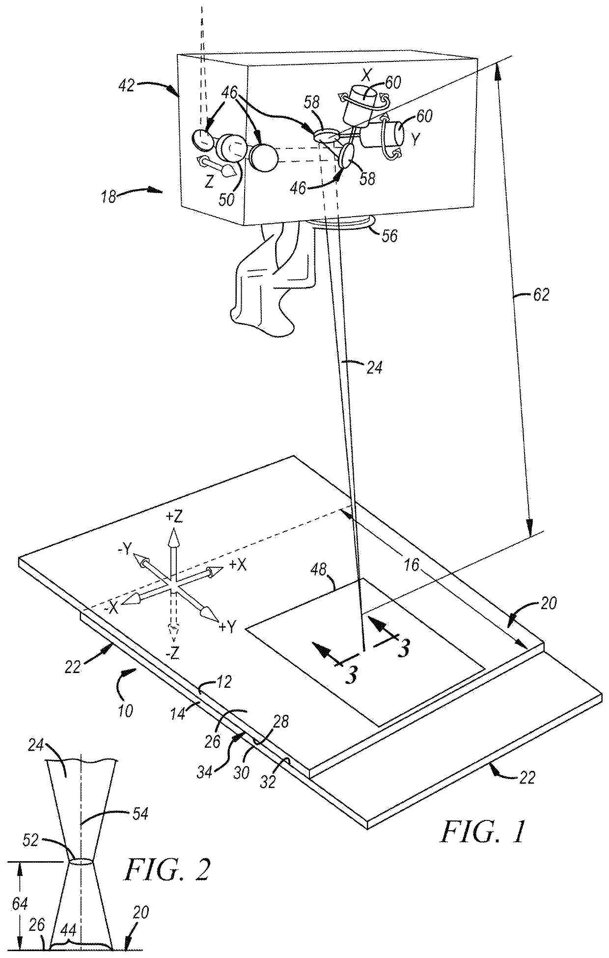
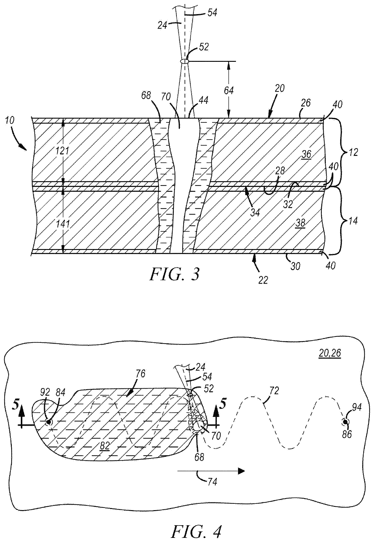
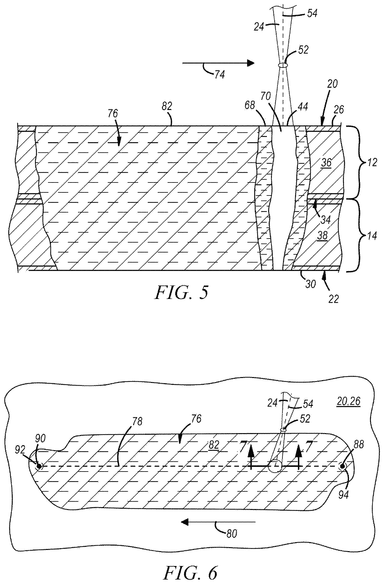
[0040]The disclosed method of laser welding two or more stacked-up metal workpieces involves advancing a laser beam—and, in particular, the beam spot of the laser beam—relative to a top surface of the workpiece stack-up along multiple overlapping weld paths during formation of the final laser weld joint. Each of the multiple weld paths may serve a particular function when traced by the laser beam that contributes to the integrity and quality of the laser weld joint including, for example, initially forming penetrating molten workpiece material in the form of an elongated melt puddle, working the elongated melt puddle once it has been formed, and optionally conditioning the melt puddle and / or the solidified laser weld joint to provide the laser weld joint with a smooth top surface. By carrying out the laser welding method in this way—as opposed to advancing the laser beam once along a single beam travel pattern—the laser weld joint can be formed in a more deliberate and efficient man...


PUM

PropertyMeasurementUnit
Raaaaaaaaaaa
Raaaaaaaaaaa
melting pointaaaaaaaaaa

Abstract

A method of laser welding together two or more overlapping metal workpieces (12, 14, or 12, 150, 14) included in a welding region (16) of a workpiece stack-up (10) involves advancing a beam spot (44) of a laser beam (24) relative to a top surface (20) of the workpiece stack-up along a first weld path (72) in a first direction (74) to form an elongated melt puddle (76) and, then, advancing the beam spot (44) of the laser beam (24) along a second weld path (78) in a second direction (80) that is opposite of the first direction while the elongated melt puddle is still in a molten state. The first weld path and the second weld path overlap so that the beam spot of the laser beam is conveyed through the elongated melt puddle when the beam spot is advanced along the second weld path.

Description

TECHNICAL FIELD[0001]The technical field of this disclosure relates generally to a method for laser welding together metal workpieces such a workpiece stack-up comprised of two or more steel workpieces, a workpiece comprised of two or more aluminum workpieces, or a workpiece stack-up comprised of two or more magnesium workpieces.INTRODUCTION[0002]Laser welding is a metal joining process in which a laser beam is directed at an assembly of stacked-up metal workpieces to provide a concentrated heat source capable of effectuating a weld joint between the constituent metal workpieces. In general, complimentary flanges or other bonding regions of two or more metal workpieces are first aligned, fitted, and stacked relative to one another such that their faying surfaces overlap and confront to establish one or more faying interfaces. A laser beam is then directed at an accessible top surface of the workpiece stack-up within a welding region spanned by the overlapping portion of the workpiec...

Claims


Application Information

Patent Timeline
Patent Type & Authority Patents(United States)
IPC IPC(8): B23K26/244B23K26/082B23K26/354B23K26/06B23K26/08B23K26/322B23K103/08B23K103/10B23K103/04
CPCB23K26/244B23K26/0643B23K26/0665B23K26/082B23K26/0876B23K26/322B23K26/354B23K2103/04B23K2103/10B23K2103/15B23K26/323
Inventor YANG, DAVIDTAO, WU
Owner GM GLOBAL TECH OPERATIONS LLC
Why Eureka
Try Eureka