
Two-stage precombustion chamber for large bore gas engines

a gas engine and precombustion chamber technology, applied in combustion engines, spark plugs, electrical equipment, etc., can solve the problems of high nox in the prechamber of fuel rich engines, and achieve the effects of reducing nox levels in gas engines, preventing flame quenching, and promoting flame propagation speed

Active Publication Date: 2014-03-06
PROMETHEUS APPLIED TECH
View PDF15 Cites 15 Cited by
  • Summary
  • Abstract
  • Description
  • Claims
  • Application Information

AI Technical Summary

Benefits of technology

The patent describes a two-stage precombustion chamber for gas engines that can reduce NOx levels. The chamber has two stages, with the first stage enclosing a smaller volume and containing a primary electrode and ground electrodes to form electrode gaps. The second stage encloses a larger volume and contains one or more second stage holes. The two stages are connected by one or more first stage holes. The first fuel concentration in the first stage is higher than the second fuel concentration. The two-stage precombustion chamber can also have a fuel admission point and a fuel admission point for each stage. The method involves introducing fuel in-filling streams into the prechamber chamber and generating a spark to ignite the fuel-air mixture. The technical effect of this invention is to provide a more effective way of reducing NOx levels in gas engines.

Problems solved by technology

A drawback of this type of system is that a fuel rich prechamber generates very high NOx and even though the main chamber generates very low NOx the combined amount remains higher than the legislated amount.

Method used


Image

  • Two-stage precombustion chamber for large bore gas engines
  • Two-stage precombustion chamber for large bore gas engines
  • Two-stage precombustion chamber for large bore gas engines

Examples


Embodiment Construction

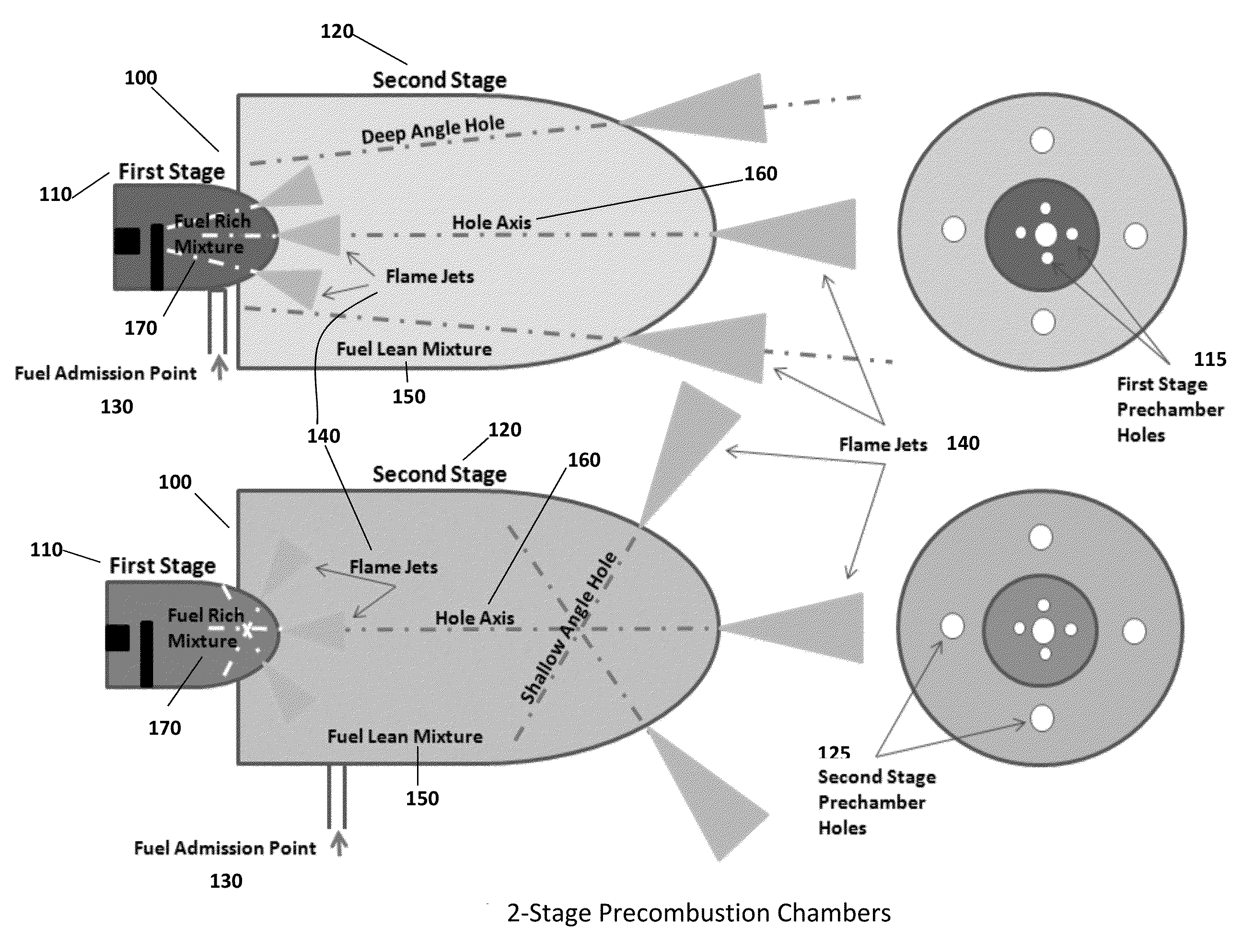
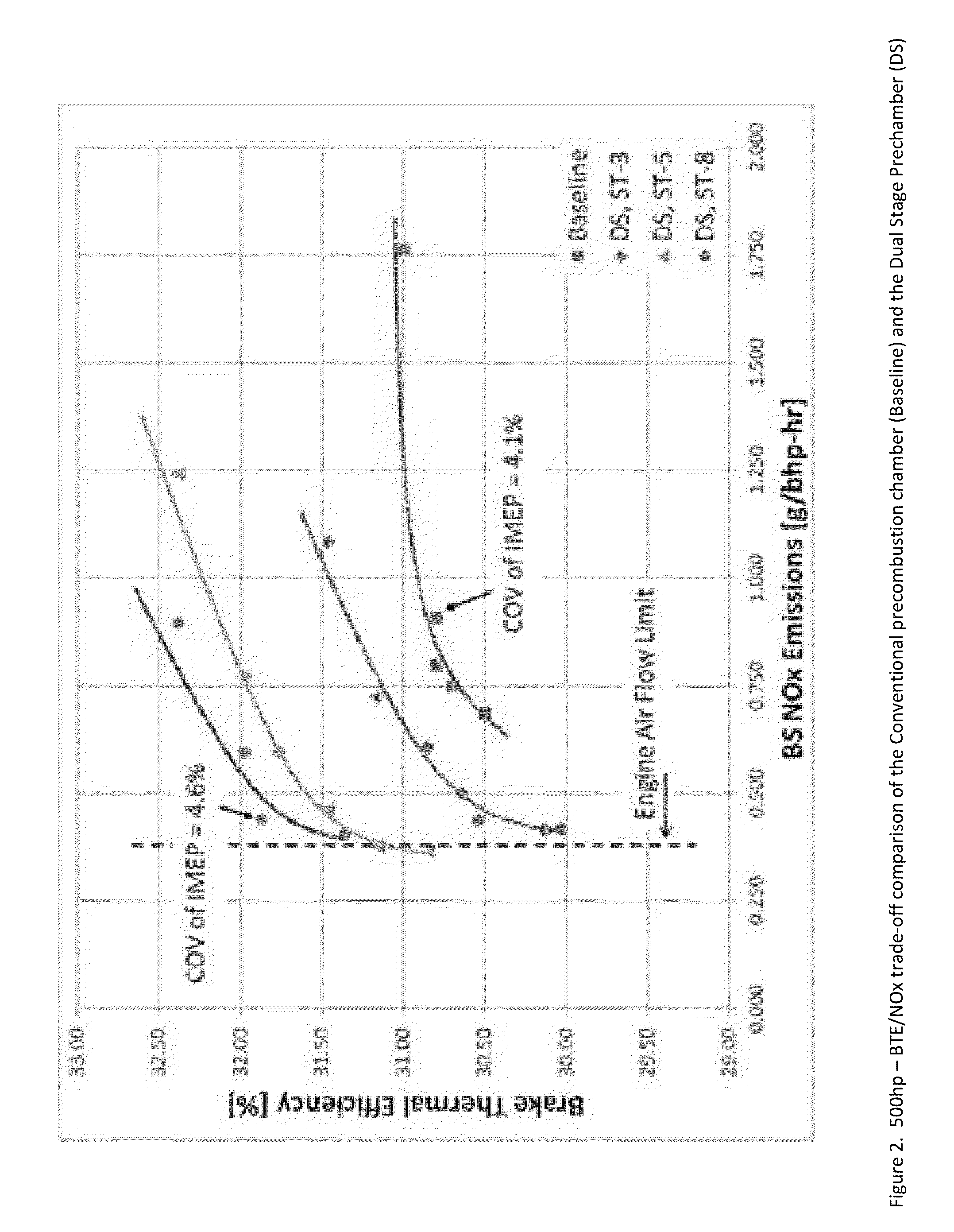
[0024]In certain embodiments, the two-stage precombustion chamber 100 concept disclosed herein, may be used to reduce engine NOx levels, with fueled precombustion chambers, while maintaining comparable engine power output and thermal efficiency.

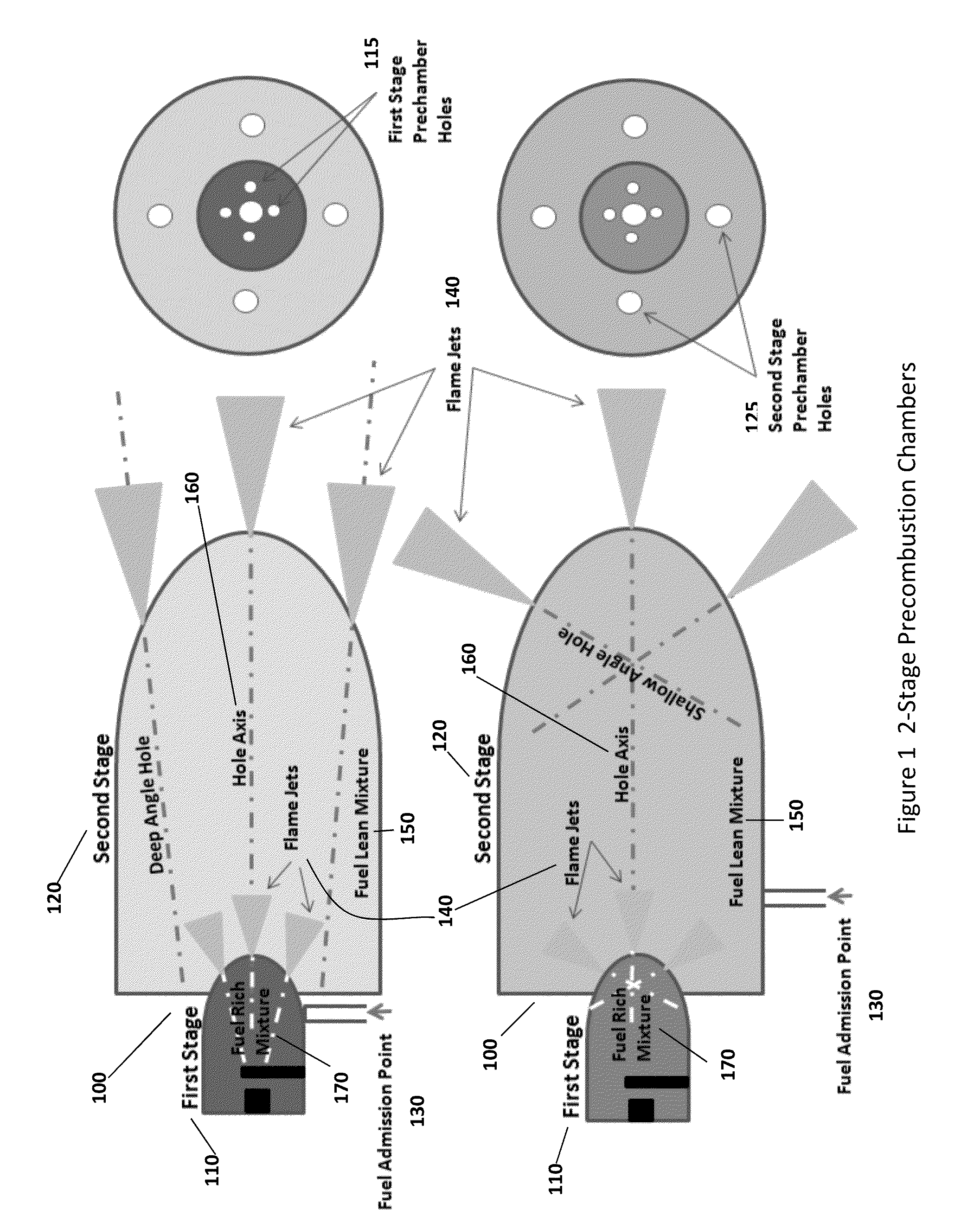
[0025]Certain embodiments provide a method and a structure to achieve more effective combustion with leaner mixtures resulting in lower NOx. In certain embodiments as shown in FIG. 1, conventional precombustion chambers may be modified so that a first stage of combustion 110 occurs in a relatively small volume, with a relatively fuel rich mixture 170, and a second stage of combustion 120 occurs in a relatively larger volume with a relatively fuel lean mixture 150. In certain embodiments, a more efficient overall combustion characterized by low levels of NOx formation can be achieved by the two-stage precombustion chamber 100 system while generating very high energy flame jets 140 emerging from the second prechamber stage 120 into the main com...


PUM


Abstract

In certain embodiments, a two-stage precombustion chamber may be used to reduce engine NOx levels, with fueled precombustion chambers, while maintaining comparable engine power output and thermal efficiency. One or more fuel admission points may be located in either the first prechamber stage or the second prechamber stage. A more efficient overall combustion characterized by low levels of NOx formation may be achieved by a two-stage precombustion chamber system while generating very high energy flame jets emerging from the second prechamber stage into the main combustion chamber. A first prechamber stage may be substantially smaller than a second prechamber stage. The volumes and aspect ratios of the two prechamber stages, along with the location of the electrodes within the first stage prechamber, the holes patterns, angles and the separate fueling, may be selected to create a distribution of fuel concentration that is substantially higher in the first stage prechamber compared to the second prechamber stage.

Description

I. CROSS-REFERENCE TO RELATED APPLICATIONS[0001]This application claims priority of U.S. Patent Application No. 61 / 697,628, entitled “Two-Stage Precombustion Chamber For Large Bore Gas Engines,” and filed Sep. 6, 2012; which is related to U.S. patent application Ser. No. 13 / 602,148, entitled “Method and apparatus for achieving high power flame jets while reducing quenching and autoignition in prechamber spark plugs for gas engines,” and filed on Sep. 1, 2012 and International Patent Application Number PCT / US2012 / 53568, entitled “Method and apparatus for achieving high power flame jets while reducing quenching and autoignition in prechamber spark plugs for gas engines,” and filed on Sep. 1, 2012, both of which claim priority to U.S. Patent Application No. 61 / 573,290, entitled “Method and apparatus for achieving high power flame jets while reducing quenching and autoignition in prechamber spark plugs for gas engines,” and filed on Sep. 3, 2011. This application is also related to Inte...

Claims


Application Information

Patent Timeline
Patent Type & Authority Applications(United States)
IPC IPC(8): F02B19/12
CPCF02B19/12F02B19/108F02B19/16F02B19/1009F02B19/1014H01T13/54F02B23/04F02B23/0675F02B17/005F02B23/0672F02B19/1095Y02T10/12F02B1/04
Inventor TOZZI, LUIGI P.SOTIROPOULOU, MARIA EMMANUELLALEPLEY, DAVID THOMAS
Owner PROMETHEUS APPLIED TECH
Learn More