Internal combustion engine comprising an exhaust gas recirculation system

a technology of exhaust gas recirculation and combustion engine, which is applied in the direction of machines/engines, mechanical equipment, non-fuel substance addition to fuel, etc., can solve the problems of reducing combustion temperature and oxygen concentration, limiting nox generation, and significant heat transfer from hot exhaust gas to coolant, etc., to achieve better mixing of egr gas, less expensive, and better cooling of egr gas

Active Publication Date: 2012-11-06
VOLVO TRUCK CORP
View PDF12 Cites 6 Cited by
  • Summary
  • Abstract
  • Description
  • Claims
  • Application Information

AI Technical Summary

Benefits of technology

[0025]With this arrangement, EGR gas flowing from the exhaust manifold goes through the EGR turbine prior to entering the EGR cooler. Due to the pressure reduction occurring in the turbine, the EGR gas temperature is lowered, for example by as much as 100° C. Consequently, the EGR gas temperature at the EGR cooler inlet is lower than in the prior art engines. This makes it possible to reduce the load on the engine cooling system and to obtain a lower EGR gas temperature at the intake manifold inlet, which means an even more reduced NOx level in the exhaust gas. Moreover, to achieve this goal, the invention does not require a large and cumbersome radiator. It has to be noticed that, even if an air to water heat exchanger is still present in the engine to cool EGR gas, the heat rejection to the engine cooling system is however lowered thanks to the invention, since the expansion through the EGR turbine makes it possible to save a significant part of the vehicle cooling capacity. The fact that the EGR turbine is of the variable geometry type allows an optimal control of the EGR gas temperature and pressure reductions through the EGR turbine. Indeed, the flow of EGR gas can thus be regulated by varying the geometry of the turbine. Indeed, a direct effect of varying the turbine geometry is to vary the pressure drop of the flow of EGR gases through the EGR turbine, which influences the flow of gases in the EGR circuit compared to flow of gas in the main exhaust line.

Problems solved by technology

This results in lowering the combustion temperature and oxygen concentration and, as a consequence, limits NOx generation as NOx is generated by oxygen and high temperature.
Consequently, the heat transferred from the hot exhaust gas to the coolant can be significant, which can be detrimental to the cooling capacity of the vehicle cooling system.
Tighter NOx emission regulations will therefore result in vehicle cooling systems needing more cooling power.
Therefore, coolant pump design could be problematic, and fuel consumption could be significantly increased as cooling fans may have to be engaged more often to meet the extra cooling need.
Another technical issue that has to be taken into account is the engine pressure differential.
However, under specific engine operating conditions, exhaust backpressure can be lower than intake pressure (i.e. dP is negative) or not high enough.
Consequently, under these engine operating conditions, no or too little EGR gas is rerouted into the intake manifold, and therefore NOx emissions cannot be reduced under the level imposed by regulations.
This positive exhaust to intake pressure difference will also affect engine efficiency and increase fuel consumption.
Moreover, since a single turbine is provided on the exhaust line to drive two compressors, namely an intake air compressor and an EGR gas compressor, the engine thermodynamic efficiency is not optimized.
However, a vehicle has a complex structure which includes a large number of components (engine, cooling system, suspension system, transmission system, hydraulic system etc.) which are very tightly arranged so as to minimize the overall size of the vehicle.
The consequence is that the space dedicated to accommodate the radiator can be severely limited.
In addition to being complex, such a structure also lacks compactness.
This line, which is branched-off the waste-gate of the turbocharger, therefore forms a kind of EGR line, but it has the disadvantage that the EGR flow is directly linked to the amount of gas discharged from the waste-gate.
Therefore, it is not possible to control independently the flow of gases through the turbine of the turbocharger and the flow of EGR.
Therefore, for certain operating conditions, it is not possible to fully optimize the engine's operation.
This prevents the EGR turbine from getting energy from only one part of the exhaust manifold, receiving only a few exhaust pulses, which would lead to an irregular driving of said turbine and to a poor efficiency.

Method used


Image

  • Internal combustion engine comprising an exhaust gas recirculation system
  • Internal combustion engine comprising an exhaust gas recirculation system
  • Internal combustion engine comprising an exhaust gas recirculation system

Examples


Embodiment Construction

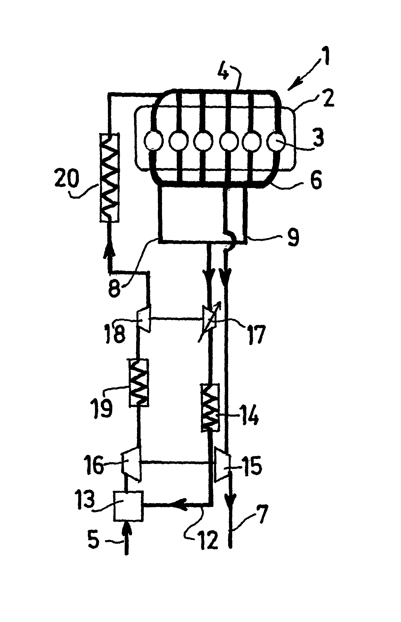
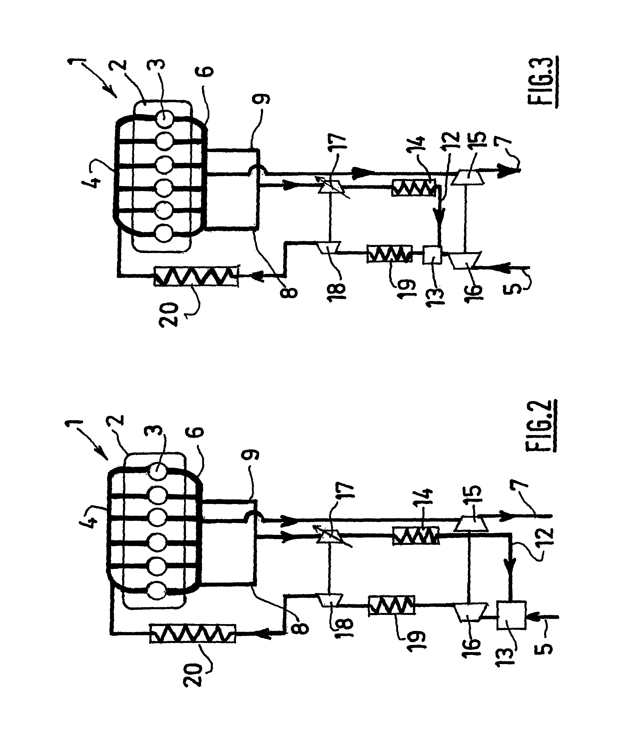
[0053]An internal combustion engine 1 typically comprises an engine block 2 defining a plurality of cylinders 3, namely six cylinders in the embodiments illustrated in the figures. The number and arrangement of cylinders as illustrated in the drawings is of course purely indicative.

[0054]Intake air is carried towards an intake manifold 4 feeding the cylinders 3, through an air intake line 5. The gas formed in each cylinder 3 can be collected by an exhaust manifold 6 arranged in two halves. An exhaust line 7 connected to the exhaust manifold 6 carries one part of the gas (exhaust gas) towards the atmosphere. The other part of the gas (EGR gas) is carried by two circuits 8, 9, each connected to one half of the exhaust manifold 6. These circuits 8, 9 meet and form a single EGR line 12 whose outlet comes out in an EGR mixer 13 connected to the air intake line 5. In the shown embodiments, the EGR line is also provided with an EGR cooler 14 using the engine coolant, located downstream of ...


PUM


Abstract

An internal combustion engine includes a plurality of cylinders, an air intake line and an exhaust line collecting exhaust gas. The engine also includes an EGR line for rerouting a part of the exhaust gas from the exhaust line towards the air intake line and at least a first turbocharger comprising a first turbine driven by the exhaust gas flowing towards the atmosphere, linked to a first compressor located on the air intake line. The engine further includes a variable geometry EGR turbine located on the EGR line, driven by the EGR gas flowing in the EGR line. Thus, thanks to the pressure reduction occurring in the turbine, the EGR gas temperature is lowered, and less cooling power from the engine cooling system is required to cool down the EGR.

Description

BACKGROUND AND SUMMARY[0001]The present invention relates to an internal combustion engine comprising an exhaust gas recirculation system, especially an internal combustion engine dedicated to personal vehicles or industrial applications, such as industrial vehicles or machines.[0002]In many countries, environmental regulations impose an upper limit in engine NOx (nitrogen oxide and nitrogen dioxide) emissions, and in future regulations, this limit will again be reduced.[0003]One of the conventional ways of decreasing the level of NOx emissions in internal combustion engines is to recirculate a portion of the exhaust gas back to the engine cylinders. This results in lowering the combustion temperature and oxygen concentration and, as a consequence, limits NOx generation as NOx is generated by oxygen and high temperature. Cooling the exhaust gas recirculation (EGR) gas before reintroduction into the engine further reduces NOx emissions as this allows the introduction into the cylinde...

Claims


Application Information

Patent Timeline
Patent Type & Authority Patents(United States)
IPC IPC(8): F02B33/44
CPCF02B29/0412F02M25/0711F02M25/0713F02M25/0739F02B37/013F02M25/07F02B37/004F02M25/0748F02M25/0731Y02T10/121Y02T10/146F02M26/00F02M26/08F02M26/10F02M26/28F02M26/34F02M26/42Y02T10/12
Inventor AUFFRET, NICOLASDRONNIOU, NICOLAS
Owner VOLVO TRUCK CORP
Why Eureka
Try Eureka