Reductant quality system including rationality diagnostic

a quality system and reductant technology, applied in the direction of electrical control, separation processes, instruments, etc., can solve problems affecting efficiency, and achieve the effect of reducing nox and reducing nox levels in exhaust gas

Inactive Publication Date: 2015-06-09
GM GLOBAL TECH OPERATIONS LLC
View PDF2 Cites 5 Cited by
  • Summary
  • Abstract
  • Description
  • Claims
  • Application Information

AI Technical Summary

Benefits of technology

[0004]According to at least one exemplary embodiment, an exhaust gas treatment system includes a reductant delivery system configured to introduce a reductant solution to an exhaust gas flowing through the exhaust gas treatment system. A selective catalyst reduction device is configured to chemically react with the reductant solution to induce a NOx conversion that reduces a level of NOx in the exhaust gas. A reductant quality sensor is configured to generate an electrical signal indicating a quality of the reductant solution. The exhaust gas treatment system further includes a rationality diagnostic control module configured to rationalize the reductant quality sensor based on a comparison between the quality of the reductant solution and the NOx conversion.
[0005]According to another exemplary embodiment, a rationality diagnostic control module to rationalize a reductant quality sensor that determines a quality of a reductant solution delivered by an exhaust treatment system comprises a memory unit configured to store a lookup table. The lookup table stores a plurality of quality parameters corresponding to a quality of a reductant solution and a NOx conversion threshold value corresponding to each quality parameter. An electronic NOx conversion unit is configured to determine a NOx conversion differential value based on a measured NOx conversion parameter and a modeled NOx conversion parameter. An electronic rationalization unit is configured to compare the quality of the reductant solution to the quality parameters of the lookup table to determine a corresponding NOx conversion threshold value. The electronic rationalization unit is further configured to rationalize the reductant quality sensor based on a comparison of the NOx conversion differential value and the determined NOx conversion threshold value.
[0006]In yet another exemplary embodiment, a method of rationalizing a reductant quality sensor included in an exhaust treatment system comprises introducing a reductant solution to an exhaust gas flowing through the exhaust gas treatment system. The method further includes inducing a NOx conversion that reduces a level of NOx in the exhaust gas in response to the reductant solution. The method further includes determining a quality of the reductant solution, and rationalizing the reductant quality sensor based on a comparison between the quality of the reductant solution and the NOx conversion.

Problems solved by technology

The quality of the reductant solution may affect the efficiency at which the SCR device effectively reduces the NOx emissions.

Method used


Image

  • Reductant quality system including rationality diagnostic
  • Reductant quality system including rationality diagnostic
  • Reductant quality system including rationality diagnostic

Examples


Embodiment Construction

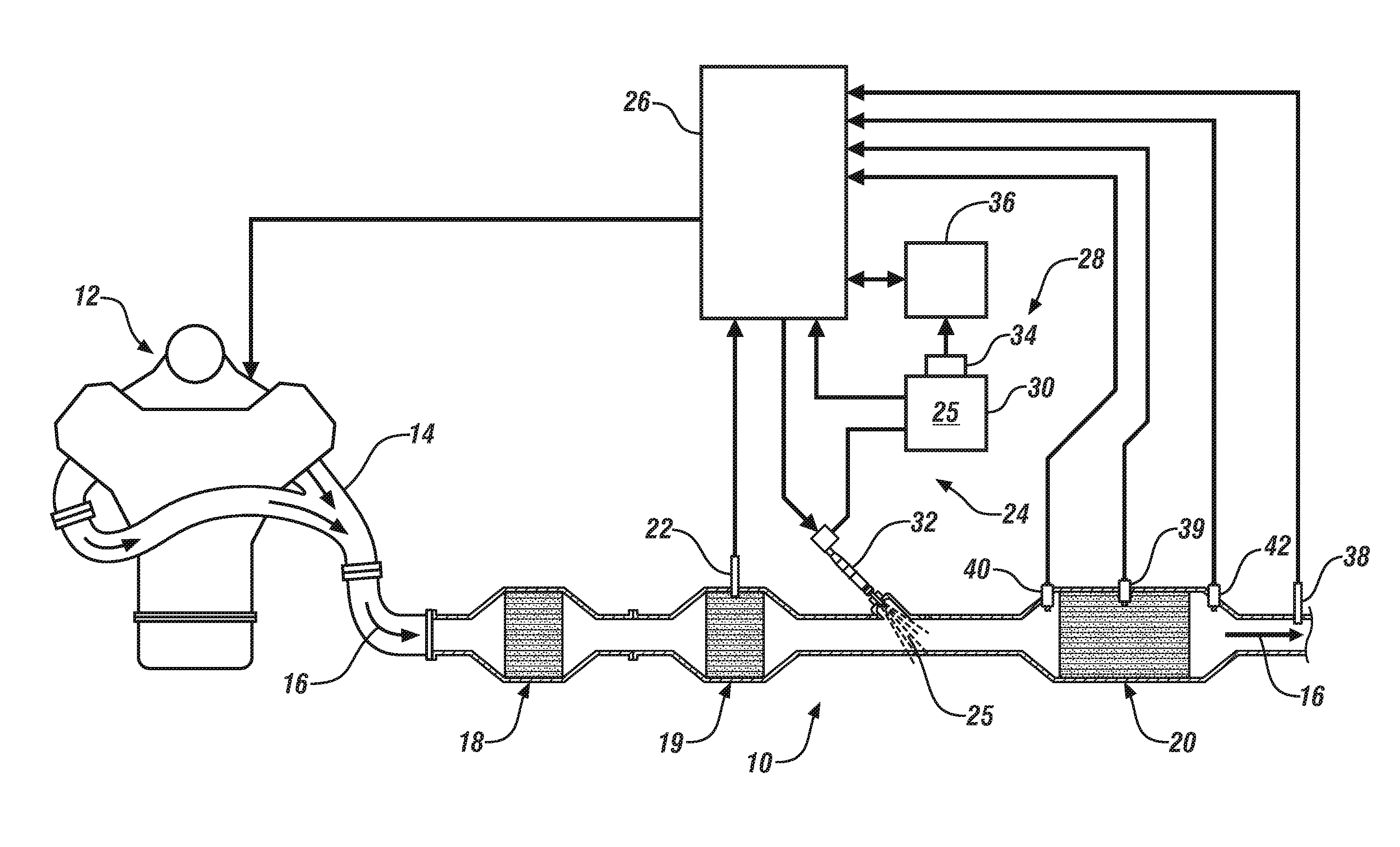
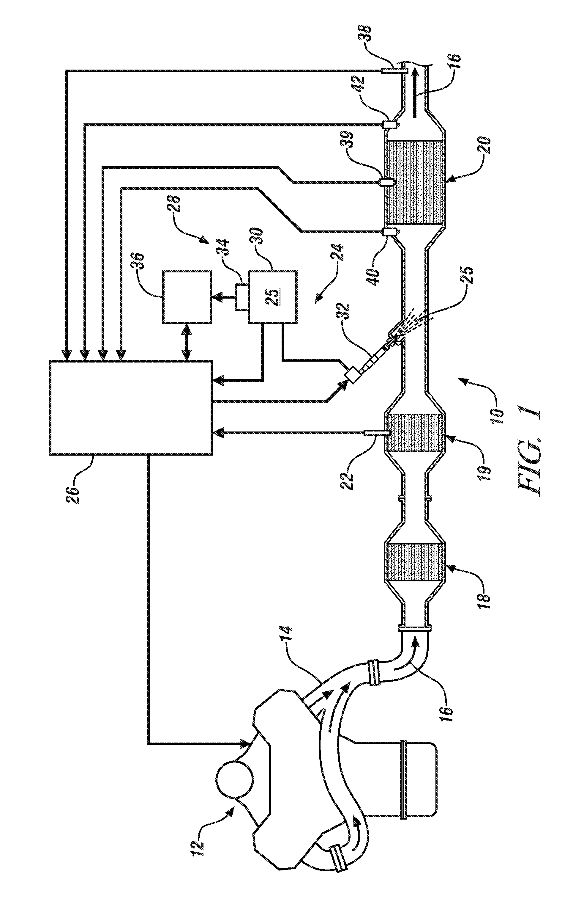
[0012]Referring now to FIG. 1, an exemplary embodiment is directed to an exhaust gas treatment system 10, for the reduction of regulated exhaust gas constituents of an internal combustion (IC) engine 12. The exhaust gas treatment system 10 described herein can be implemented in various engine systems. Such engine systems may include, for example, but are not limited to diesel engine systems, gasoline direct injection systems, and homogeneous charge compression ignition engine systems.

[0013]The exhaust gas treatment system 10 generally includes one or more exhaust gas conduits 14, and one or more exhaust treatment devices. The exhaust gas conduit 14, which may comprise of several segments, transports exhaust gas 16 from the engine 12 to the various exhaust treatment devices of the exhaust gas treatment system 10. The exhaust treatment devices include, but are not limited to, an oxidation catalyst device (“OC”) 18, a particulate filter (“PF”) 19, and a selective catalytic reduction (“...


PUM


Abstract

An exhaust gas treatment system includes a reductant delivery system configured to introduce a reductant solution to an exhaust gas flowing through the exhaust gas treatment system. A selective catalyst reduction device is configured to chemically react with the reductant solution to induce a NOx conversion that reduces a level of NOx in the exhaust gas. A reductant quality sensor is configured to generate an electrical signal indicating a quality of the reductant solution. The exhaust gas treatment system further includes a rationality diagnostic control module configured to rationalize the reductant quality sensor based on a comparison between the quality of the reductant solution and the NOx conversion.

Description

FIELD OF THE INVENTION[0001]The present disclosure relates to exhaust gas treatment systems, and more specifically, to an exhaust gas treatment system including a reductant quality system.BACKGROUND[0002]Exhaust gas emitted from an internal combustion (IC) engine, is a heterogeneous mixture that may contain gaseous emissions such as carbon monoxide (CO), unburned hydrocarbons (HC) and oxides of nitrogen (NOx) as well as condensed phase materials (liquids and solids) that constitute particulate matter. Catalyst compositions typically disposed on catalyst supports or substrates are provided in an engine exhaust system to convert certain, or all of these exhaust constituents into non-regulated exhaust gas components.[0003]Exhaust gas treatment systems typically include one or more selective catalytic reduction (SCR) devices and a reductant delivery system. The SCR devices include a substrate having a washcoat disposed thereon that operates to reduce the amount of NOx in the exhaust gas...

Claims


Application Information

Patent Timeline
Patent Type & Authority Patents(United States)
IPC IPC(8): B01D53/94F01N11/00F01N3/20G05B1/00G05D21/02G05B21/00
CPCB01D53/9495G05D21/02B01D53/90B01D53/9409F01N3/208F01N9/005F01N9/007F01N11/00F01N2550/05F01N2560/026F01N2560/14F01N2900/0412F01N2900/1621F01N2900/1622F01N2900/1818F02D41/222Y02A50/20Y02T10/12Y02T10/40
Inventor SHETNEY, JUSTIN ADAMSUN, MINCATALOGNA, JOHN A.
Owner GM GLOBAL TECH OPERATIONS LLC
Why Eureka
Try Eureka