Solar panel

a solar panel and solar energy technology, applied in the field of solar panels, can solve the problems of increasing the loss of generated power, significantly decreasing the light-receiving area of each solar cell, and reducing the light-receiving area, so as to reduce the loss of electric power, increase the light-receiving area, and enhance power generation efficiency

Active Publication Date: 2014-03-06
CASIO COMPUTER CO LTD
View PDF7 Cites 17 Cited by
  • Summary
  • Abstract
  • Description
  • Claims
  • Application Information

AI Technical Summary

Benefits of technology

[0011]The present invention is to provide a solar panel capable of enhancing power generation efficiency by increasing a light-receiving area and reducing losses of electric power due to changes of the light-receiving area.

Problems solved by technology

However, since the plurality of connection sections are provided to the outer perimeters of the solar cells in the solar panel as described above, when the plurality of connection sections are covered by a cover plate, the cover plate hides light-receiving sections on the outer perimeters of the plurality of solar cells, and therefore there is a problem in that the light-receiving area of each solar cell is significantly decreased.
Accordingly, this solar panel has problems in that the light-receiving area is decreased, losses of the generated power are increased and the power generation efficiency is low.

Method used


Image

  • Solar panel
  • Solar panel
  • Solar panel

Examples


first embodiment

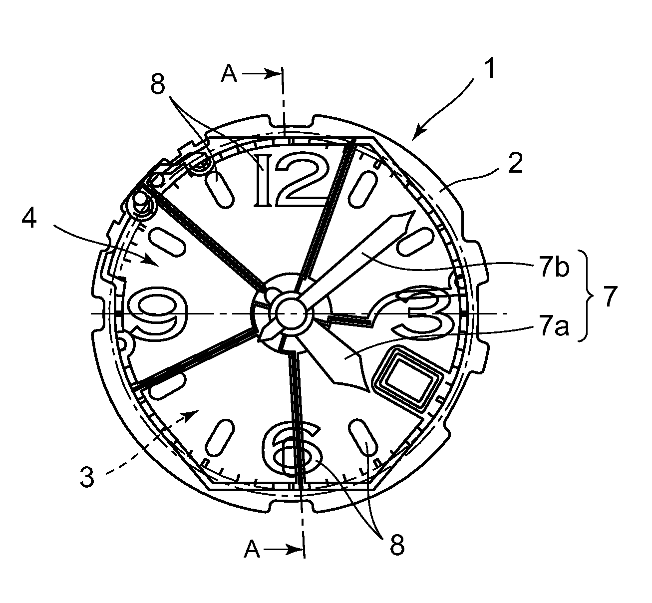
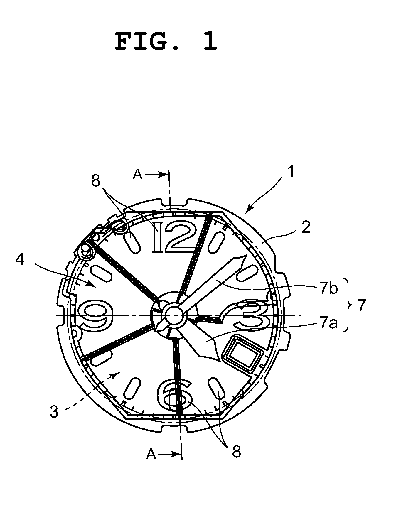
[0025]A first embodiment in which the present invention has been applied to a pointer-type wristwatch is described below with reference to FIG. 1 to FIG. 6.

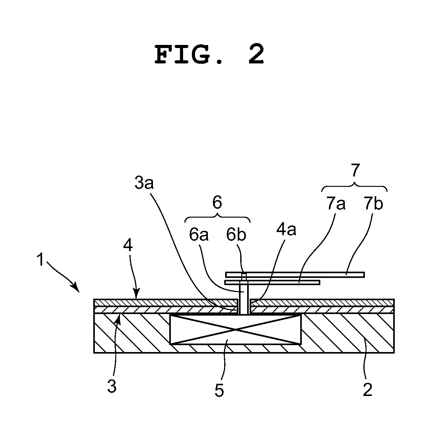
[0026]The wristwatch includes a timepiece module 1, as depicted in FIG. 1 and FIG. 2.

[0027]The timepiece module 1 has a housing 2 and is arranged in a wristwatch case (not shown).

[0028]The housing 2 has a solar panel 3 arranged on the upper surface thereof, and the solar panel 3 has a dial plate 4 arranged on the upper surface thereof, as depicted in FIG. 1 and FIG. 2.

[0029]Also, the housing 2 has a timepiece movement 5 provided therein.

[0030]The timepiece movement 5 is structured to more pointers 7 such as an hour hand 7a and a minute hand 7b by rotating a pointer shaft 6.

[0031]In this case, the dial plate 4 is made of a transparent or translucent film, and is formed in a substantially circular shape, as depicted in FIG. 1.

[0032]The dial plate 4 has hour characters 8 provided on an edge portion on the upper surface thereof with ...

second embodiment

[0115]Next, a second embodiment in which the present invention has been applied to a wristwatch is described below with reference to FIG. 7 and FIG. 8.

[0116]Note that components identical to those of the first embodiment depicted in FIG. 1 to FIG. 6 are provided with the same reference numerals for description.

[0117]As depicted in FIG. 7 and FIG. 8, a solar panel 30 of the wristwatch includes a plurality of connection sections 31 to 35 structured differently from the first embodiment. Except for this point, the solar panel 30 is identical in structure to that of the first embodiment.

[0118]That is, as depicted in FIG. 8, the plurality of connection sections 31 to 35 are each formed of a conductive paste, and connect the lower electrode 22 of one of solar cells adjacent to each other among the solar cells 11 to 16 and the upper electrode 24 of the other solar cell adjacent thereto.

[0119]In this case, among the solar cells 11 to 16 adjacent to each other, the first solar cell 11 and th...


PUM


Abstract

A solar panel of the present invention includes a plurality of solar cells arranged in a substantially circular shape, and a plurality of connection sections which are provided near a center portion where the plurality of solar cells are all close to each other, and electrically connect the plurality of solar cells. Therefore, the plurality of connection sections can be centrally placed near the center portion where the plurality of solar cells are all close to each other. As a result, a decrease in the light-receiving area due to the plurality of connection sections can be reduced, and fluctuations in the light-receiving area due to pointers moving over the solar cells can be reduced.

Description

CROSS-REFERENCE TO RELATED APPLICATION[0001]This application is based upon and claims the benefit of priority from the prior Japanese Patent Application No. 2012-194105, filed Sep. 4, 2012, the entire contents of which are incorporated herein by reference.BACKGROUND OF THE INVENTION[0002]1. Field of the Invention[0003]The present invention relates to a solar panel for use in an electronic device such as a timepiece.[0004]2. Description of the Related Art[0005]For example, in a solar panel for use in a wristwatch, a plurality of solar cells each having a power-generating layer between a lower electrode and an upper electrode are arranged in a circular shape, as described in Japanese Patent Application Laid-Open (Kokai) Publication No. 10-039057.[0006]The known solar panel is structured such that the outer perimeters of the plurality of these solar cells are electrically connected by a plurality of connection sections.[0007]This type of solar panel is structured such that, when the so...

Claims


Application Information

Patent Timeline
Patent Type & Authority Applications(United States)
IPC IPC(8): H01L31/05
CPCH01L31/0508G04C10/02Y02E10/50H01L31/0465H01L31/046
Inventor SAITO, YUTA
Owner CASIO COMPUTER CO LTD
Why Eureka
Try Eureka