Brake for Electric Motor

a technology for electric motors and brakes, applied in mechanical devices, mechanical energy handling, transportation and packaging, etc., can solve the problems of noisy clutch-type brakes, insufficient stopping power for emergency stops, and narrow range of braking torque that a specific clutch-type brake can variably apply, so as to reduce magnetic flux

Active Publication Date: 2014-03-06
OTIS ELEVATOR CO
View PDF12 Cites 5 Cited by
  • Summary
  • Abstract
  • Description
  • Claims
  • Application Information

AI Technical Summary

Benefits of technology

[0023]In accordance with yet another aspect of the disclosure, a brake for applying a braking torque upon a machine shaft is provided. The brake may include a stator having a plurality of shunts and a plurality of teeth radially disposed thereabout, a rotor with an electrically conductive inner layer having a plurality of magnets and a plurality of ferromagnetic poles radially disposed thereabout and an actuator assembly disposed within the stator. The shunts may be movable with respect to the teeth. The rotor may be rigidly coupled to the machine shaft and rotatably disposed about the stator such that the magnets and the ferromagnetic poles are in close proximity to the teeth. The actuator assembly may be configured to selectively move the shunts relative to the teeth into one of an engagement state and a free engagement state. The shunts may enable variable magnetic flux between the teeth and the ferromagnetic poles during the engagement state. The shunts may further substantially reduce magnetic flux between the teeth and the ferromagnetic poles during the free engagement state.

Problems solved by technology

Due to its dependency on friction, clutch-type brakes can be noisy.
Furthermore, the range of braking torque that a specific clutch-type brake can variably apply is relatively narrow.
For example, a clutch-type brake cannot provide enhanced or sufficiently more stopping power for emergency stops, or the like.
Conversely, a clutch-type brake cannot provide reduced stopping power for normal stops than with emergency stops.
A typical clutch-type brake is limited to its rated torque which is further dictated by the invariable mechanical limits of the brake, material composition of its friction pads, and the like.
Accordingly, it follows that clutch-type brakes offer less overall control or variation of the braking torque.
The manufacturing and installation of clutch-type brakes onto the frame and shaft of an elevator can be complex and costly.
Correspondingly, making adjustments to a pre-existing clutch-type braking system may also be costly and difficult to perform.
Regardless of the degree of maintenance performed, however, long-term use of clutch-type brakes could result in burnished surfaces on bearing frames, splinted shaft ends, and the like.
Furthermore, the pure mechanical nature of clutch-type brakes makes it difficult to integrate the brake with any other useful controls or functions, such as speed detection, position detection, rescue encoding, or any other subsystem functions.

Method used


Image

  • Brake for Electric Motor
  • Brake for Electric Motor
  • Brake for Electric Motor

Examples


Embodiment Construction

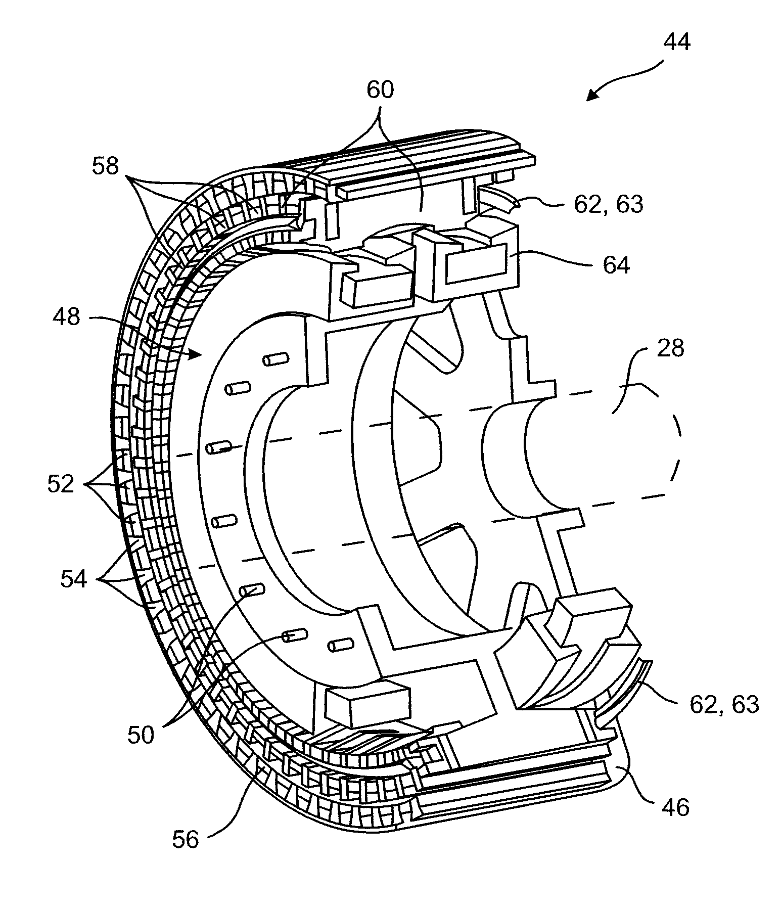
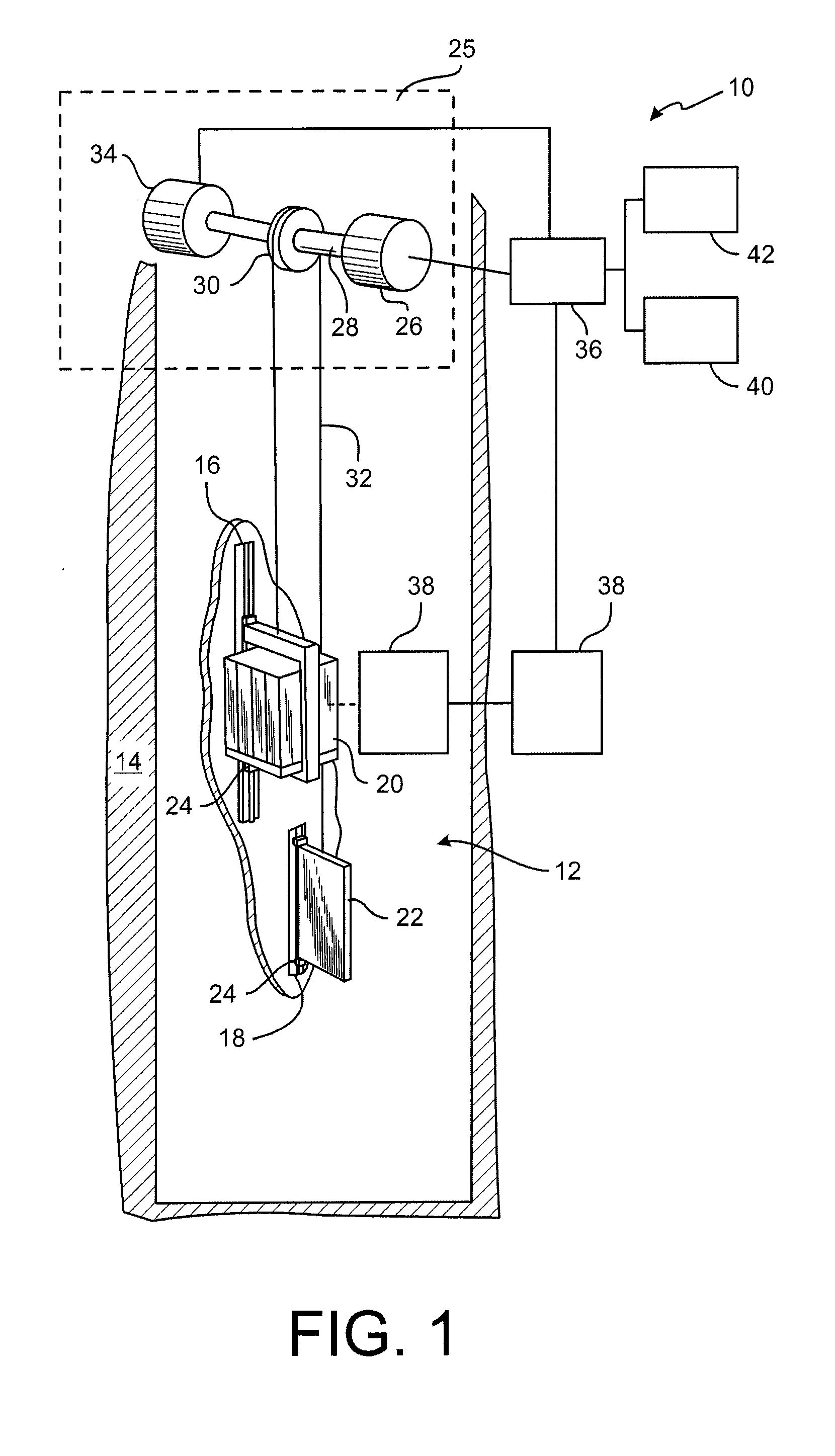
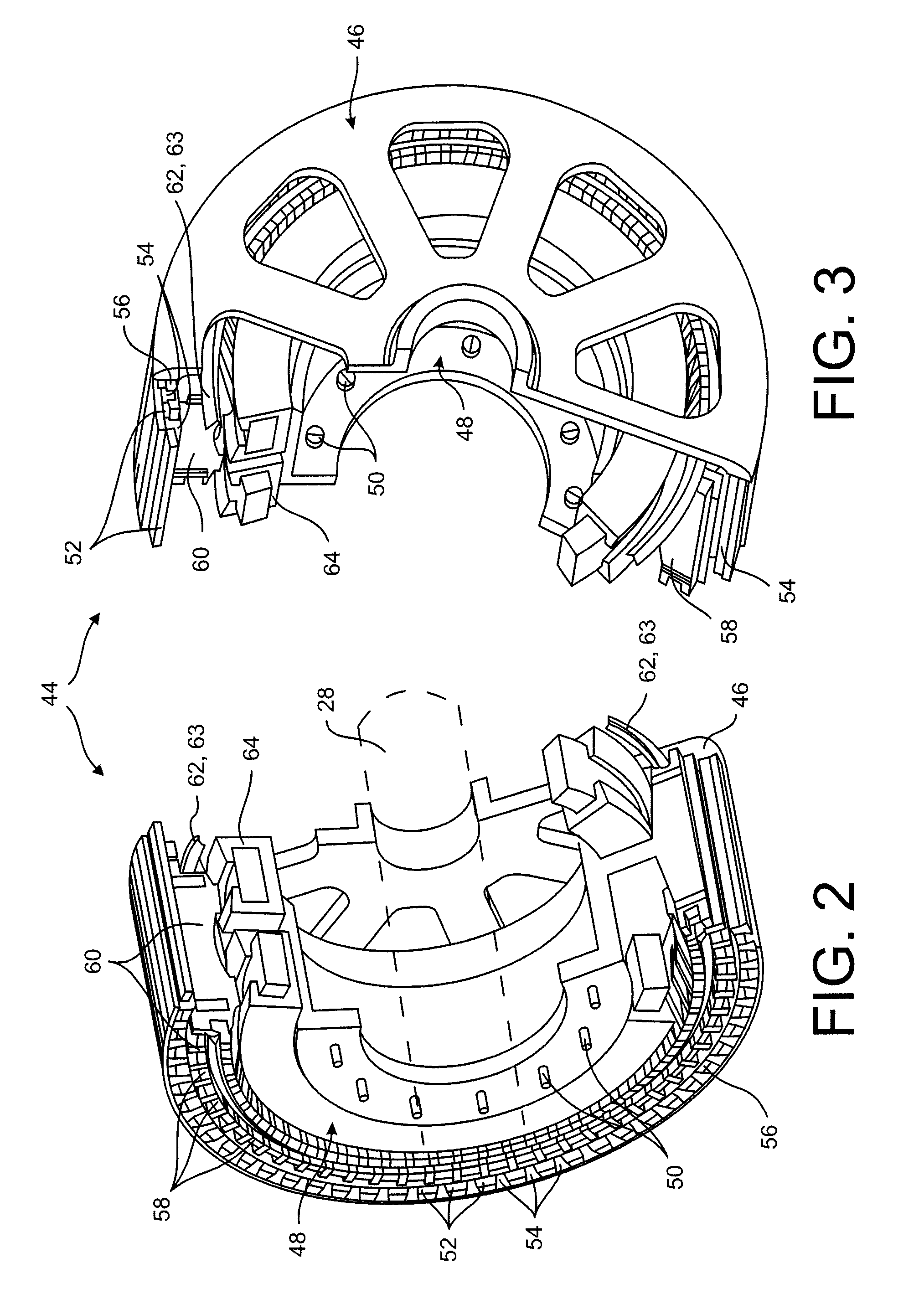
[0040]Referring now to FIG. 1, a schematic diagram of an exemplary elevator system 10 is provided. It is to be understood that the version of the elevator system 10 shown in FIG. 1 is for illustrative purposes only and to present background for some of the various components of a general elevator system. Other components of an elevator system unnecessary for an understanding of the present disclosure are not described.

[0041]As shown in FIG. 1, the elevator system 10 may reside fully or partially in a hoistway 12 that is vertically disposed within a building 14. The hoistway 12 may generally be a hollow shaft provided within a central portion of the building 14 with multiple hoistways being provided if the building is of sufficient size and includes multiple elevators. Extending substantially the length of the hoistway 12 may be rails 16, 18 along which an elevator cab 20 as well as counterweights 22 may be slidably mounted. While not depicted in detail in FIG. 1, one of ordinary ski...


PUM


Abstract

A brake is provided. The brake may include a rotor having a plurality of magnets and a plurality of ferromagnetic poles radially disposed thereabout, and a stator having a plurality of shunts and a plurality of teeth radially disposed thereabout. At least one of the plurality of shunts and the plurality of teeth may be configured to selectively move between an engagement state and a free engagement state. The teeth may be configured to generate magnetic flux with the ferromagnetic poles so as to generate a braking torque during the engagement state. The shunts may be configured to redirect the magnetic flux therethrough and reduce the braking torque between the teeth and the ferromagnetic poles during the free engagement state.

Description

FIELD OF THE DISCLOSURE[0001]The present disclosure generally relates to a brake for an electric motor, and more particularly, to magnetic braking devices for applying a braking torque upon a shaft of an electric motor.BACKGROUND OF THE DISCLOSURE[0002]Gearless machines such as elevators or other belt-driven systems typically employ a mechanical or electromechanical braking system to stop or temporarily hold a particular motion. Electromechanical brakes of elevators, for instance, generally employ a clutch-type braking mechanism for supplying a holding or braking torque that is sufficient for slowing or holding an elevator cab at a fixed position. The braking torque supplied by clutch-type brakes is mechanically produced by the friction that is generated between a rotating brake disk that is rigidly attached to a machine shaft and a set of friction pads that are releasably placed in contact with a surface of the brake disk. The engagement or disengagement of the friction pads is ele...

Claims


Application Information

Patent Timeline
Patent Type & Authority Applications(United States)
IPC IPC(8): F16D63/00
CPCF16D63/00H02K49/10H02K7/106H02K2213/09
Inventor PIECH, ZBIGNIEWROGERS, KYLE W.MARVIN, DARYL J.
Owner OTIS ELEVATOR CO
Why Eureka
Try Eureka