Permanent magnet type motor and method of producing permanent magnetic type motor

A technology of permanent magnets and motors, applied in electric components, magnetic circuit rotating parts, magnetic circuits, etc., can solve problems such as increased magnetic flux, increased vibration or noise, and increased torque fluctuations

Inactive Publication Date: 2006-04-12
MITSUBISHI ELECTRIC CORP
View PDF0 Cites 3 Cited by
  • Summary
  • Abstract
  • Description
  • Claims
  • Application Information

AI Technical Summary

Problems solved by technology

[0016] However, in the above-mentioned rotor structure of Conventional Example 3, if Figure 16 As shown, the thickness of the rotor core part 12a across the gap 5 and each permanent magnet 14 increases, and the magnetic impedance decreases. The

Method used


Image

  • Permanent magnet type motor and method of producing permanent magnetic type motor
  • Permanent magnet type motor and method of producing permanent magnetic type motor
  • Permanent magnet type motor and method of producing permanent magnetic type motor

Examples


Embodiment Construction

[0045] The best way to practice the invention

[0046] Implementation form 1

[0047] Hereinafter, Embodiment 1 of the present invention will be described with reference to the drawings.

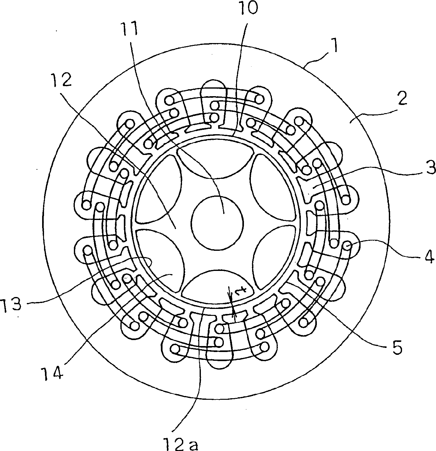
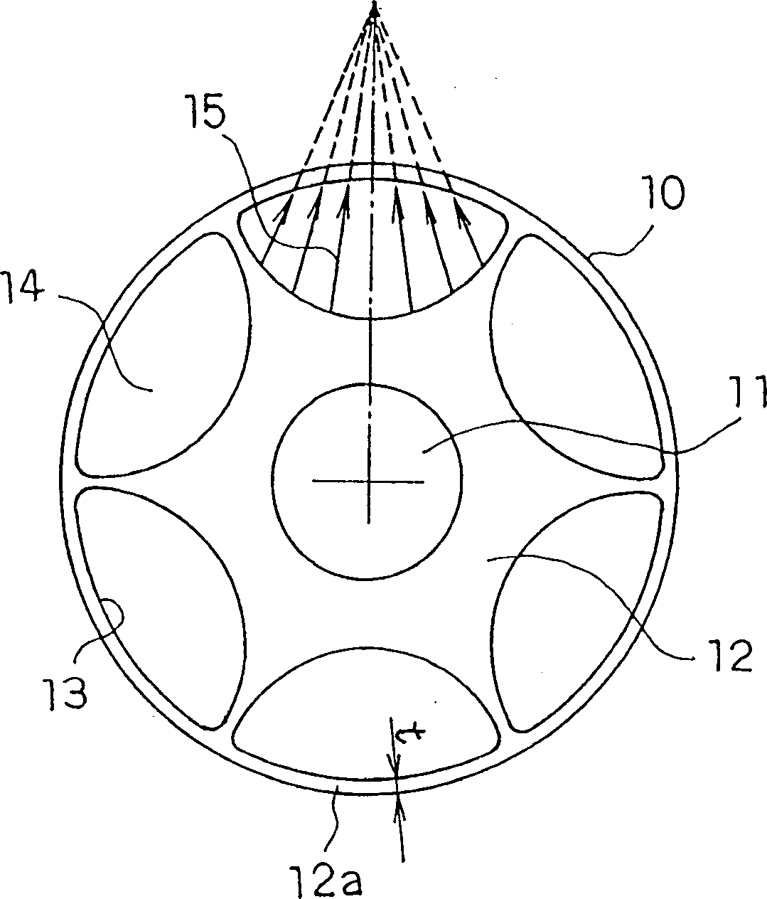
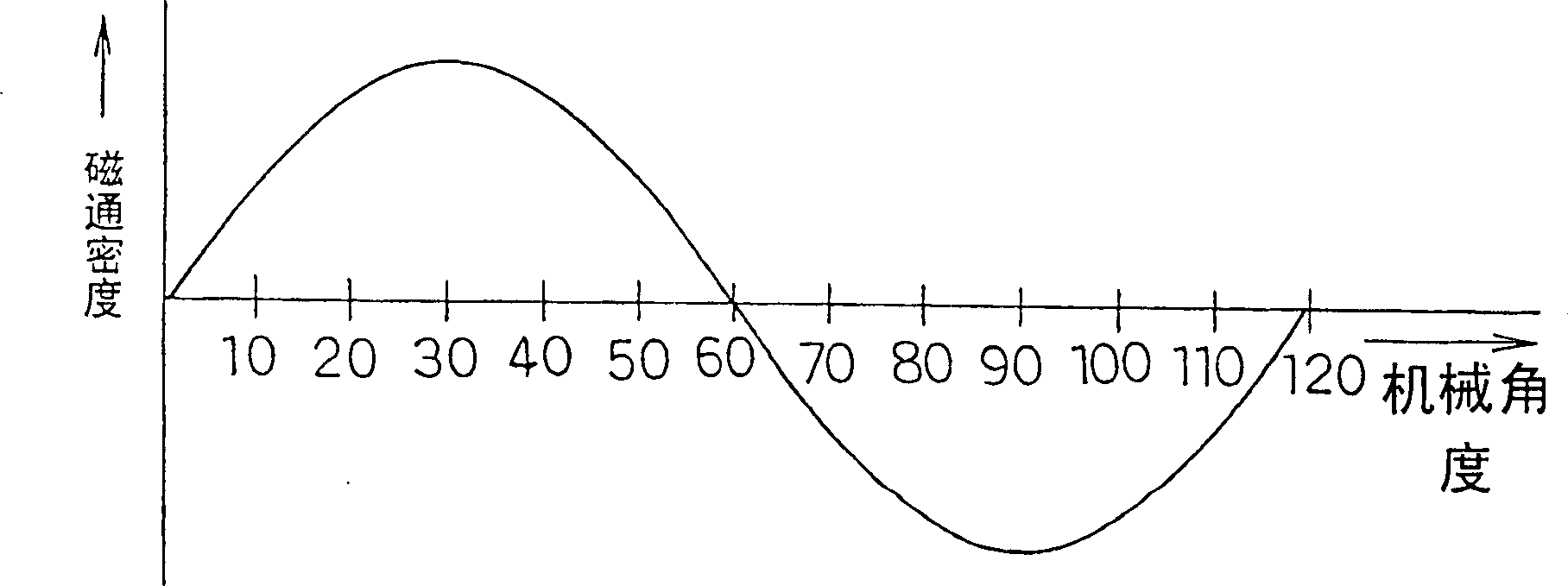
[0048] Figure 1~4 To represent the view of implementation form 1, figure 1 is a view of a permanent magnet type motor, figure 2 is a view showing the magnetic orientation state of the permanent magnet, image 3 is the magnetic flux density distribution diagram, Figure 4 for figure 1 An enlarged view of the main part.

[0049] figure 1 Among them, the stator 1 is composed of an annular stator core 2 , a plurality of teeth 3 formed on the stator core 2 , and a coil 4 wound around the teeth 3 . The stator 1 is, for example, a distributed winding stator with multiphase stator windings.

[0050]The rotor 10 is rotatably arranged on the inner side of the stator 1 via the gap 5 . The rotor 10 is structured to have a rotating shaft 11 and a rotor core 12 provided on the outer periphe...


PUM


Abstract

A permanent magnet type motor with a permanent magnet, capable of reducing vibration and noise without lowering the motor efficiency, which comprises a stator (1) having multi-phase stator windings, and a rotor (10) disposed inside the stator in opposed relation through air gaps, and having a stator core (12) and permanent magnets (14) installed in the stator core, wherein the permanent magnets (14) are so shaped that their section at right angles with the axis of rotation is convexed on both inner and outer diameter sides and that the focus of magnetism orientation in each magnet pole of the permanent magnet (14) is disposed outside the rotor (10).

Description

technical field [0001] The present invention relates to a permanent magnet type motor used in, for example, an air conditioner or a compressor for a refrigerator, and a method for manufacturing the same. Background technique [0002] Existing example 1 [0003] Figure 9 It is a view showing a conventional permanent magnet type motor. [0004] Figure 9 Among them, the stator 1 is composed of a ring-shaped stator core 2, a plurality of teeth 3 formed on the stator core 2, and a coil 4 wound on the teeth 3. The stator 1 is, for example, a distributed winding stator with a multiphase stator winding. [0005] On the inner side of the stator 1 , a rotor 10 is rotatably arranged via a gap 5 . Such a rotor 10 has a rotating shaft 11 and a rotor core 12 provided on the rotating shaft 11 . [0006] As shown in the figure, in the permanent magnet type motor using permanent magnets in the rotor of the motor, a permanent magnet 14 with a circular arc-shaped cross section is inserte...

Claims


Application Information

Patent Timeline
IPC IPC(8): H02K1/27H02K1/22H02K29/03
CPCH02K1/278H02K1/276H02K29/03H02K1/27
Inventor 田岛庸贺及川智明风间修增本浩二加藤政纪马场和彦
Owner MITSUBISHI ELECTRIC CORP
Why Eureka
Try Eureka