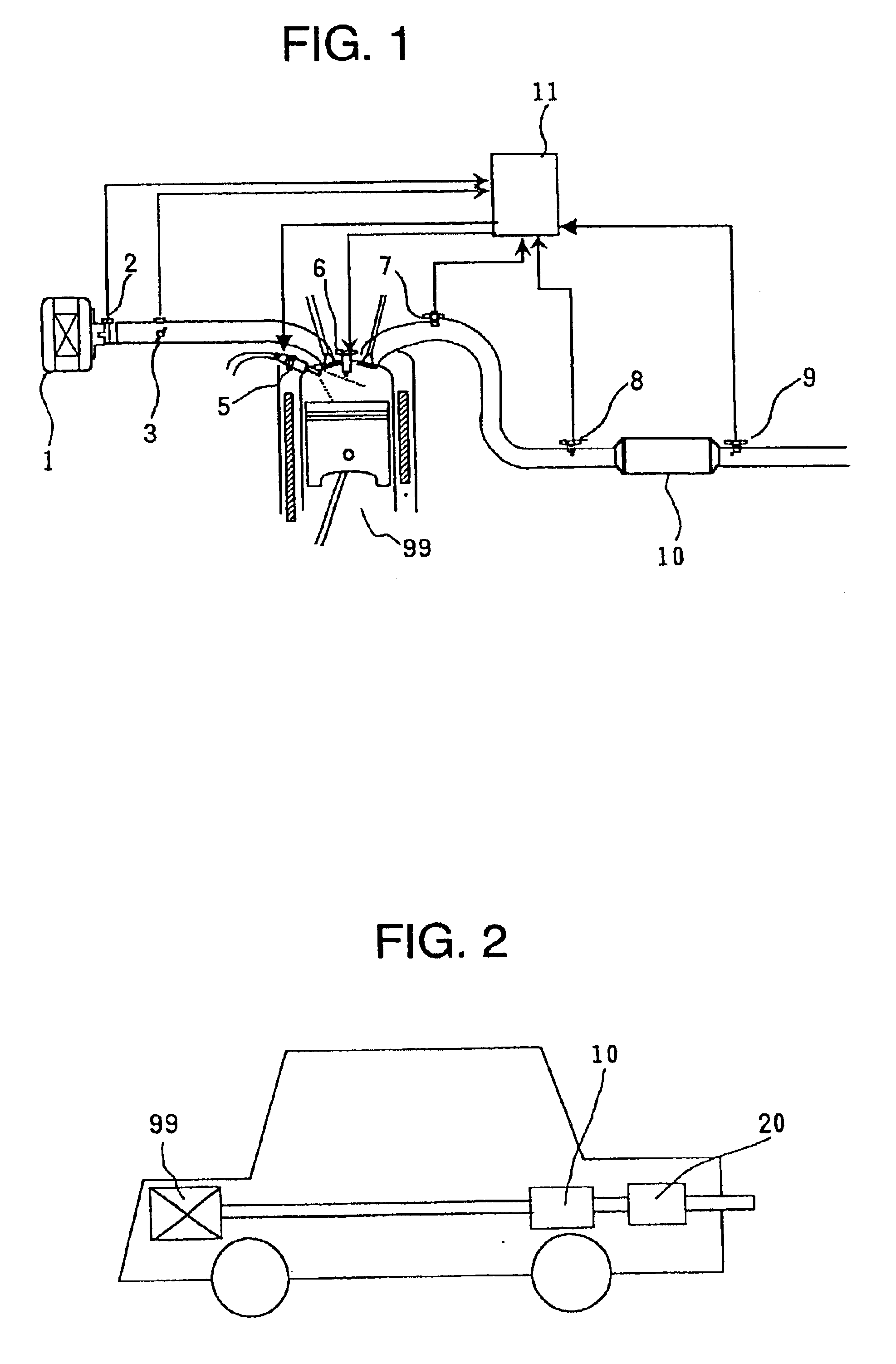
Internal combustion engine exhaust gas purification apparatus, exhaust gas purification process and exhaust gas purification catalyst

a technology of exhaust gas purification and exhaust gas, which is applied in the direction of physical/chemical process catalysts, separation processes, arsenic compounds, etc., can solve the problems of undesired small specific surface area of the porous carrier itself, poor dispersibility of active components, etc., and achieve the effect of improving the heat resistance and sox resistance of the catalys

Inactive Publication Date: 2005-01-11
HITACHI LTD
View PDF24 Cites 8 Cited by
  • Summary
  • Abstract
  • Description
  • Claims
  • Application Information

AI Technical Summary

Benefits of technology

B and P are present in the form of simple substances or oxides or composite oxides with at least one member selected from alkali metals and Al, and seem to serve to capture NOx in the oxidizing atmosphere, play a role of attracting CO, hydrocarbons, etc. as reducing agents onto the catalyst surface and serve to further improve the heat resistance and the SOx resistance of the catalyst. By controlling mixing sequence of B or P or firing temperature, etc. duri...

Problems solved by technology

In case the amount of supported porous carrier is less than 0.3 moles, the dispersibility of active components becomes ...

Method used


Image

  • Internal combustion engine exhaust gas purification apparatus, exhaust gas purification process and exhaust gas purification catalyst

Examples


example 1

A cordierite honeycomb (400 cells / inc2) was coated with a slurry prepared from alumina powder and alumina precursor and made acidic by nitric acid, dried and fired to obtain an alumina coat honeycomb as coated with 1.5 moles of alumina per 1 l of the apparent honeycomb volume. The alumina coat honeycomb was impregnated with a mixed solution of dinitrodiamine Pt nitric acid solution and Rh nitrate solution, dried at 200° C. and then fired at 600° C. Then, the supported Pt and Rh-contained honeycomb was impregnated with a mixed solution of Na nitrate solution, Mn nitrate solution and Pd nitrate solution, dried at 200° C. and then fired at 600° C. Thus, Example catalyst 1 containing 0.0022 parts by mole of Rh, 0.014 parts by mole of Pt, 0.8 parts by mole of Na, 0.2 parts by mole of Mn and 0.014 parts by mole of Pd in terms of metal elements on the basis of 1.5 parts by mole of alumina was prepared. The catalyst will be hereinafter expressed as 0.8 NaMnPd—RhPt / Al2O3. Likewise, Example C...

example 2

In the same manner as in Example 1, Example Catalysts 42 to 47 were prepared by adding Cu, Co or Ni to Example Catalysts 21 and 36, respectively, and evaluated according to Test Example 1. Amounts of supported Cu, Co and Ni were 0.1 part by mole each in terms of metal elements on the basis of 1.5 parts by mole of alumina.

Test Results

Test results are shown in Table 3. Example Catalysts containing Co, Ni or Cu had higher activities than those of Comparative Example Catalysts 1 to 14 shown in Table 1.

TABLE 3NOx eliminationefficiency (%)Catalyst300° C.400° C.500° C.Example Catalyst 42NaMgMnPd—RhPt0.1Cu / Al2O3939996Example Catalyst 43NaMgMnPd—RhPt0.1Co / Al2O3949995Example Catalyst 44NaMgMnPd—RhPt0.1Ni / Al2O3959997Example Catalyst 45LiNaKMnPd—RhPt0.1Cu / Al2O3879593Example Catalyst 46LiNaKMnPd—RhPt0.1Co / Al2O3869694Example Catalyst 47LiNaKMnPd—RhPt0.1Ni / Al2O3849993

example 3

In the same manner as in Example 1, Example Catalysts 48 to 51 were prepared by adding Ti or Si to Example Catalysts 21 and 36, respectively. Amounts of supported Ti and Si were 0.1 parts by mole each in terms of metal elements on the basis of 1.5 parts by mole of alumina.


PUM

PropertyMeasurementUnit
Fractionaaaaaaaaaa
Fractionaaaaaaaaaa
Volumeaaaaaaaaaa

Abstract

Nitrogen oxides contained in an exhaust gas emitted from a lean-burn engine-mounted internal combustion engines are eliminated with a high efficiency.
In an exhaust gas purification apparatus and process for eliminating nitrogen oxides contained in a combustion exhaust gas emitted from an internal combustion engine with a reducing gas such as carbon monoxide, hydrocarbons, etc. contained in the exhaust gas in the presence of a catalyst, a catalyst comprising all of Rh, Pt and Pd, at least one member selected from alkali metals and alkaline earth metals, and Mn or its compound, supported on a porous carrier is used.

Description

TECHNICAL FIELDThe present invention relates to an exhausts gas purification apparatus, an exhaust gas purification process and an exhaust gas purification catalyst with high elimination efficiency of NOx from NOx-containing exhaust gases such as combustion exhaust gases from internal combustion engines such as automobile engines, etc.BACKGROUND ARTLean-burn engines capable of bringing an air / fuel ratio into a fuel-lean stage have been nowadays regarded as promising automobile internal combustion engines from the viewpoint of reduced fuel consumption. However, the exhaust gases from such engines are in such an oxidizing atmosphere that the O2 concentration of the exhaust gases is more than a stoichiometric amount necessary for complete combustion of reducing components contained in the exhaust gases (said atmosphere will be hereinafter referred as “oxidizing atmosphere”). The conventional ternary catalysts are directed to efficient purification of NOx, HC and CO in such a reducing a...

Claims


Application Information

Patent Timeline
IPC IPC(8): B01J23/68B01J23/54B01D53/94B01J23/89B01J37/00B01J37/02B01J21/06B01J23/02B01J23/32B01J23/40B01J23/72
CPCB01D53/9422B01J23/688B01J23/8986B01D2255/1021B01D2255/1023B01D2255/1025B01D2255/202B01D2255/204B01J37/0205B01D2255/20746B01D2255/20753B01D2255/20761B01D2258/012B01D2255/2073B01D53/94
Inventor KANEEDA, MASATOOKUDE, KOJIROIIZUKA, HIDEHIROOGAWA, TOSHIONAGAYAMA, KOUSEIYAMASHITA, HISAOKITAHARA, YUICHIKURODA, OSAMUFUJITANI, MORIOHIRATSUKA, TOSHIFUMI
Owner HITACHI LTD
Why Eureka
Try Eureka