
Blind cord winder integrating with stopping control

a technology of stopping control and cord winder, which is applied in the field of control units, can solve the problems of not being able to stop the cordless blind at any position according to user needs, bead chain blinds, and inconvenient switching operation, and achieves the effect of easy component integration and installation

Inactive Publication Date: 2014-03-06
WU WEN YU
View PDF12 Cites 8 Cited by
  • Summary
  • Abstract
  • Description
  • Claims
  • Application Information

AI Technical Summary

Benefits of technology

The present invention provides a blind cord winder integrating with stopping control to minimize the blind stopping component for easy component integration and installation. The integrated mechanism allows users to stop the cordless blind at any position during lifting or lowering. It also avoids exposure of blind cords from contamination, prevents sudden dropping of the cordless blind to hurt someone below, and further reduces lifting force to open a cordless blind. The mechanism includes a spool, force-feedback mechanism, and braking cushion mechanism integrated into a single module for easy installation and user-friendly use.

Problems solved by technology

However, accidents of strangling small children by the bead chains have been occurred, therefore, blinds with bead chains have been forbidden in many countries.
Even though there are many different designs of cordless blinds, their switching operation is not as convenient as blinds with cords.
However, the cordless blinds can not be stopped at any position according to user needs.
Moreover, the exposed spool is easily contaminated when used in years where the blind cords can not easily be rolled up.
It is also time-consuming to install cordless blinds with exposed spools.

Method used


Image

  • Blind cord winder integrating with stopping control
  • Blind cord winder integrating with stopping control
  • Blind cord winder integrating with stopping control

Examples


Embodiment Construction

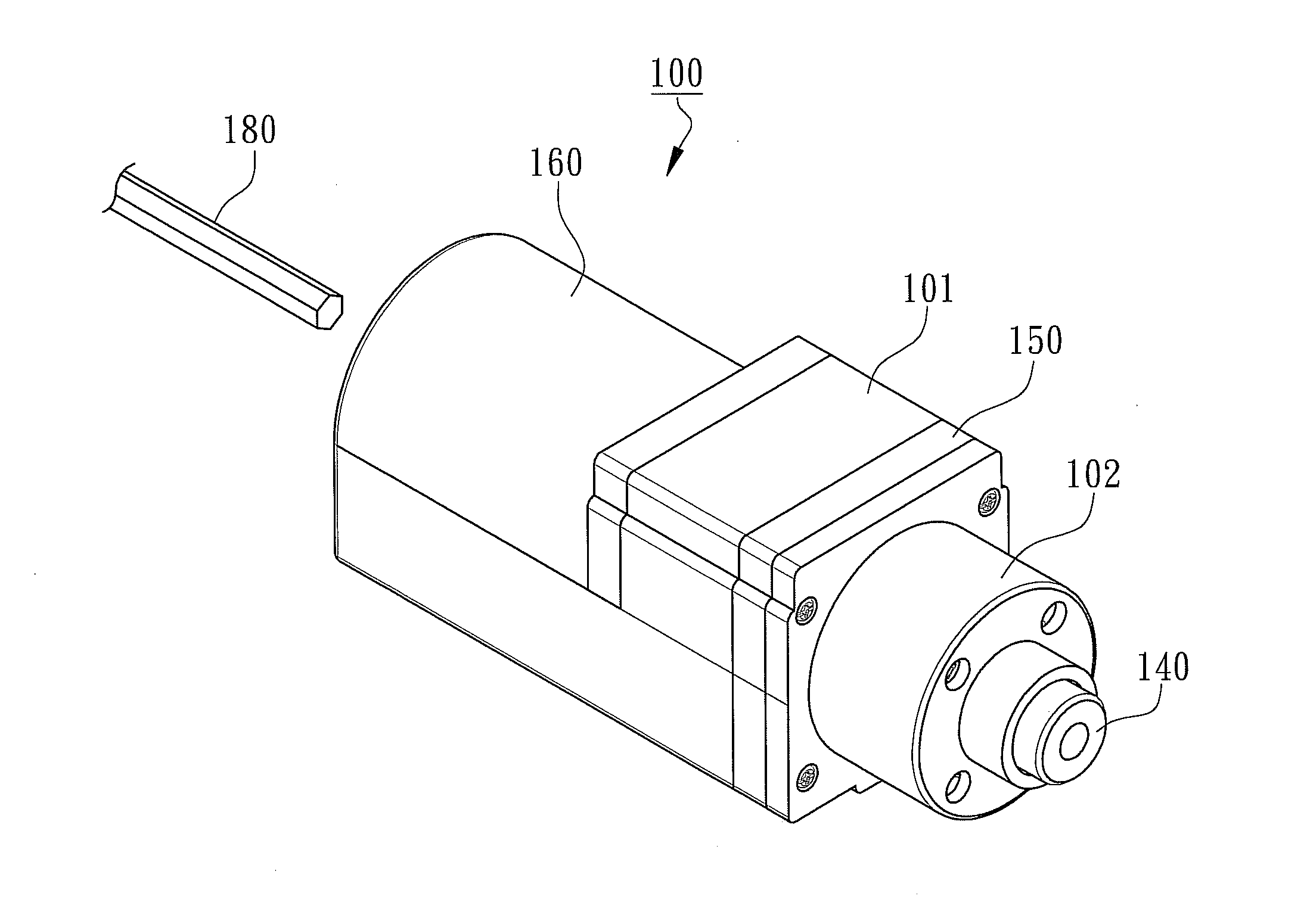
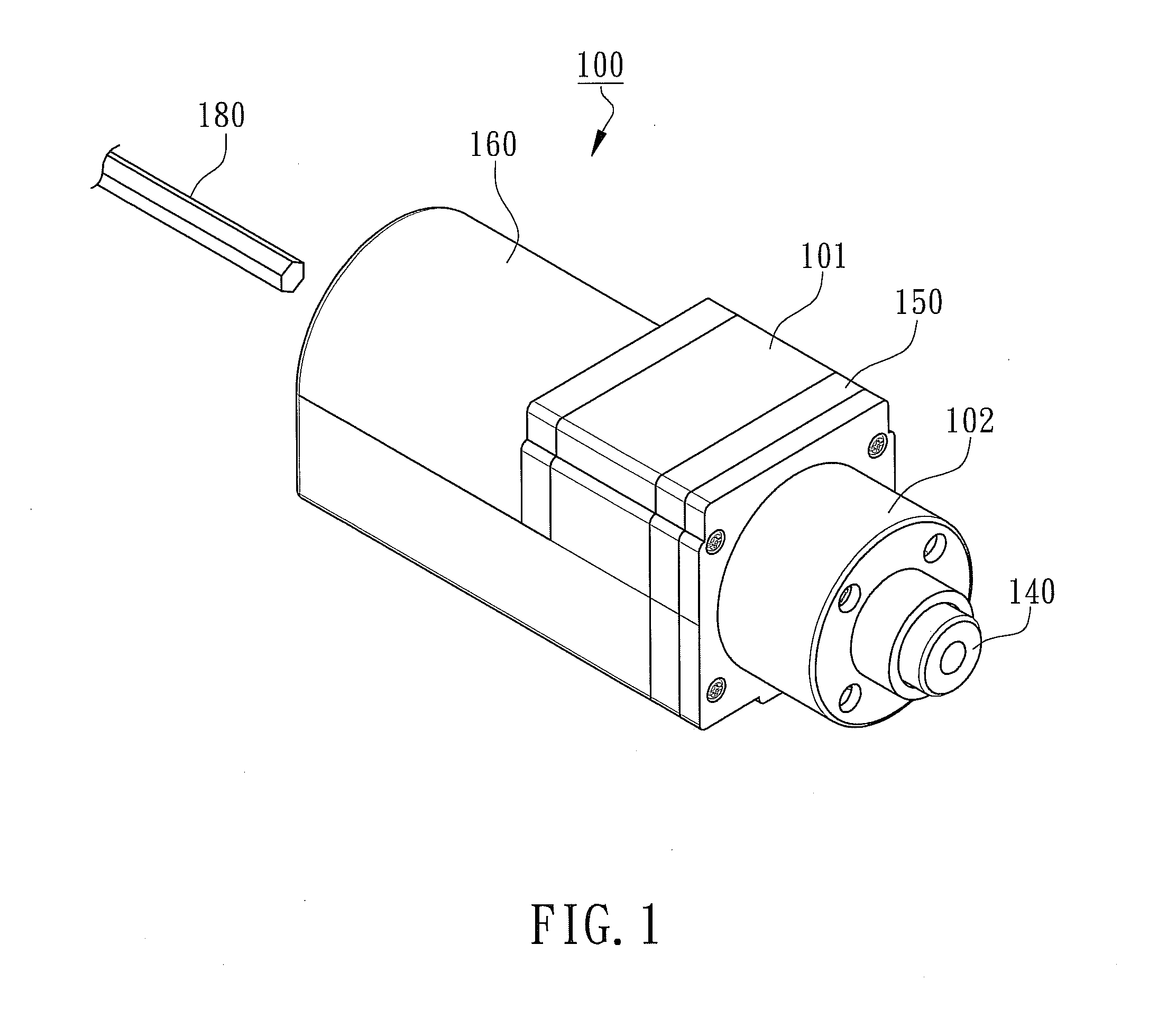
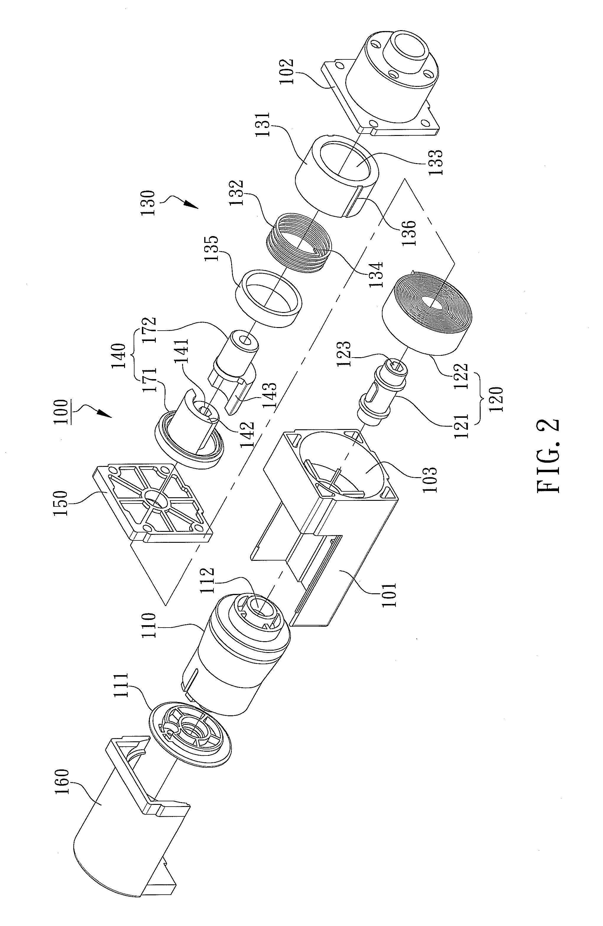
[0014]With reference to the attached drawings, the present invention is described by means of the embodiment(s) below where the attached drawings are simplified for illustration purposes only to illustrate the structures or methods of the present invention by describing the relationships between the components and assembly in the present invention. Therefore, the components shown in the figures are not expressed with the actual numbers, actual shapes, actual dimensions, nor with the actual ratio. Some of the dimensions or dimension ratios have been enlarged or simplified to provide a better illustration. The actual numbers, actual shapes, or actual dimension ratios can be selectively designed and disposed and the detail component layouts may be more complicated.

[0015]According to the preferred embodiment of the present invention, a blind cord winder 100 integrating with stopping control is disclosed in FIG. 1 for a three-dimensional view, FIG. 2 for a three-dimensional component exp...


PUM


Abstract

Disclosed is a blind cord winder integrating with stopping control to allow open / close operation of the cordless blind to lift or lower the cordless blind at any positions according to user's needs. The winder primarily comprises a spool installed inside a first compartment, a force-feedback mechanism, and a braking cushion mechanism installed inside a second compartment where the force-feedback mechanism is installed in a shaft cavity of the first compartment. The force-feedback mechanism includes a shaft sleeve and a volute spring. The braking cushion mechanism includes a friction ring, a friction spring, and a trigger sleeve. The friction ring is immovably installed inside the second compartment. The friction spring is tightly plugged into the friction ring and has an extrusion end for the trigger sleeve to trigger friction variation in a single directional rotation of the trigger sleeve.

Description

FIELD OF THE INVENTION[0001]The present invention relates to a control unit for an open / close device built-in or movably installed at window openings of a building and more specifically to a blind cord winder integrating with stopping control.BACKGROUND OF THE INVENTION[0002]Blinds of early days were controlled by blind cords where a switching controller was installed at one end of the track located on top of a blind. A bead chain or a blind cord was hanging down from the switching controller to lift or lower the blind by pulling the bead chain. However, accidents of strangling small children by the bead chains have been occurred, therefore, blinds with bead chains have been forbidden in many countries. Hence, cordless blinds become household necessities. Even though there are many different designs of cordless blinds, their switching operation is not as convenient as blinds with cords.[0003]The conventional cordless blinds hide the blind cords inside the blind with an exposed spool...

Claims


Application Information

Patent Timeline
IPC IPC(8): B65H75/30
CPCE06B9/322E06B2009/3222
Inventor WU, WEN-YU
Owner WU WEN YU
Learn More