Eureka AIR delivers breakthrough ideas for toughest innovation challenges, trusted by R&D personnel around the world.

Rectifier circuit

Inactive Publication Date: 2014-03-06
SK HYNIX INC
View PDF4 Cites 3 Cited by
  • Summary
  • Abstract
  • Description
  • Claims
  • Application Information

AI Technical Summary

Benefits of technology

The patent describes a rectifier circuit that can reduce off-voltage. This circuit has an amplification unit that generates an output voltage based on a reference voltage and a feedback voltage. A feedback unit then sends back the feedback voltage to the amplification unit, which adjusts its gain to match the change in output voltage. This results in a more accurate and reliable output voltage. Additionally, the circuit has multiple resistors with different resistance values to further improve the accuracy of the output voltage.

Problems solved by technology

The known rectifier circuit is problematic in that an error in an output level is increased due to the finite open loop gain of the operational amplifier when a plurality of unit resistors having the same resistance value is used.

Method used


Image

  • Rectifier circuit
  • Rectifier circuit
  • Rectifier circuit

Examples


Embodiment Construction

[0015]Hereinafter, a rectifier circuit according to the various embodiments will be described below with reference to the accompanying drawings through the embodiments.

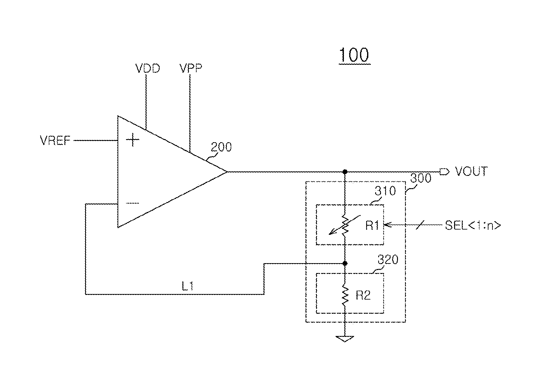
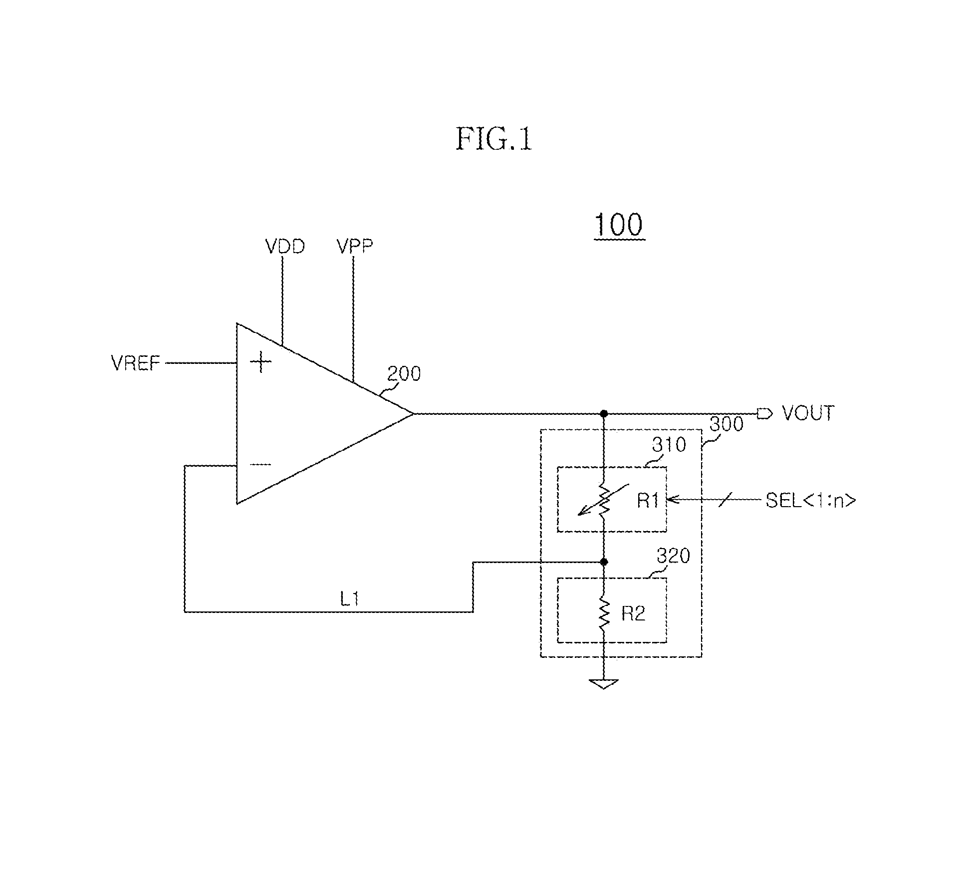
[0016]FIG. 1 is a circuit diagram of a rectifier circuit 100 in accordance with an embodiment.

[0017]As shown in FIG. 1, the rectifier circuit 100 in accordance with an embodiment may include an amplification unit 200 and a feedback unit 300.

[0018]The amplification unit 200 may be configured to generate an output voltage VOUT through an output terminal thereof in response to a reference voltage VREF and voltage at a feedback node L1.

[0019]The amplification unit 200 may be formed of an operational amplifier.

[0020]The amplification unit 200 may receive a first power source voltage VDD for operating the circuit and a second power source voltage VPP for generating the output voltage VOUT.

[0021]The reference voltage VREF may be inputted to the non-inverting terminal (+) of the amplification unit 200, and the voltage at the ...


PUM


Abstract

A rectifier circuit capable of attenuating an offset voltage wherein the rectifier circuit includes an amplification unit configured to generate an output voltage through an output terminal in response to a reference voltage and a voltage at a feedback node, a plurality of first unit resistors connected between the output terminal and the feedback node, and a plurality of second unit resistors connected between the feedback node and a ground terminal, and wherein each of the first unit resistors and each of the second unit resistors are designed to have different resistance values.

Description

CROSS-REFERENCES TO RELATED APPLICATION[0001]The present application claims priority under 35 U.S.C. §119(a) to Korean application number 10-2012-0097783, filed on Sep. 4, 2012, in the Korean Intellectual Property Office, which is incorporated herein by reference in its entirety.BACKGROUND[0002]1. Technical Field[0003]The present invention generally relates to a semiconductor circuit, and more particularly, to a rectifier circuit.[0004]2. Related Art[0005]A known rectifier circuit used in a semiconductor circuit can be configured by in series coupling an operational amplifier and unit resistors having the same resistance value. Furthermore, a large number of the unit resistors must be used in order to improve the resolution of the rectifier circuit.[0006]The known rectifier circuit is problematic in that an error in an output level is increased due to the finite open loop gain of the operational amplifier when a plurality of unit resistors having the same resistance value is used.[0...

Claims


Application Information

Patent Timeline
IPC IPC(8): H02M3/02
CPCH02M3/02H02M7/02H03F1/34H02M1/0025G05F1/565G05F1/575
Inventor CHOI, SUNG WOOK
Owner SK HYNIX INC
Why Eureka
Eureka Blog
Learn More