
Switching mode converter and method for controlling thereof

a converter and switching mode technology, applied in the direction of dc-dc conversion, power conversion systems, climate sustainability, etc., can solve the problems of components not being able to operate, the output device of the pmos is disadvantageous, and the cost of the nmos device is higher than the pmos device, so as to ensure the effect of providing a bootstrap function

Active Publication Date: 2014-03-06
SILICON WORKS CO LTD
View PDF7 Cites 33 Cited by
  • Summary
  • Abstract
  • Description
  • Claims
  • Application Information

AI Technical Summary

Benefits of technology

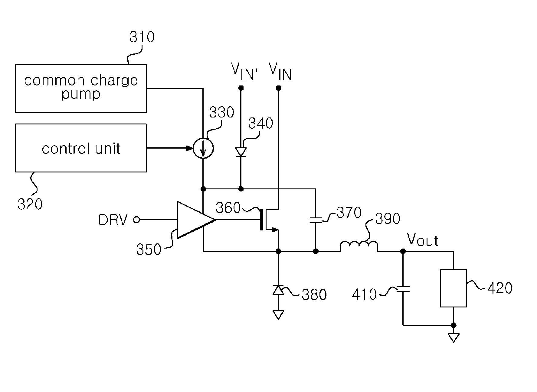
The present invention aims to solve issues in the prior art by providing a switching mode converter and method of controlling it that can safely implement a bootstrap function and control the charging of a bootstrap capacitor and the gate voltage of a switching element using a common charge pump. Additionally, the invention provides a method for providing a safe bootstrap function without adding external capacitors.

Problems solved by technology

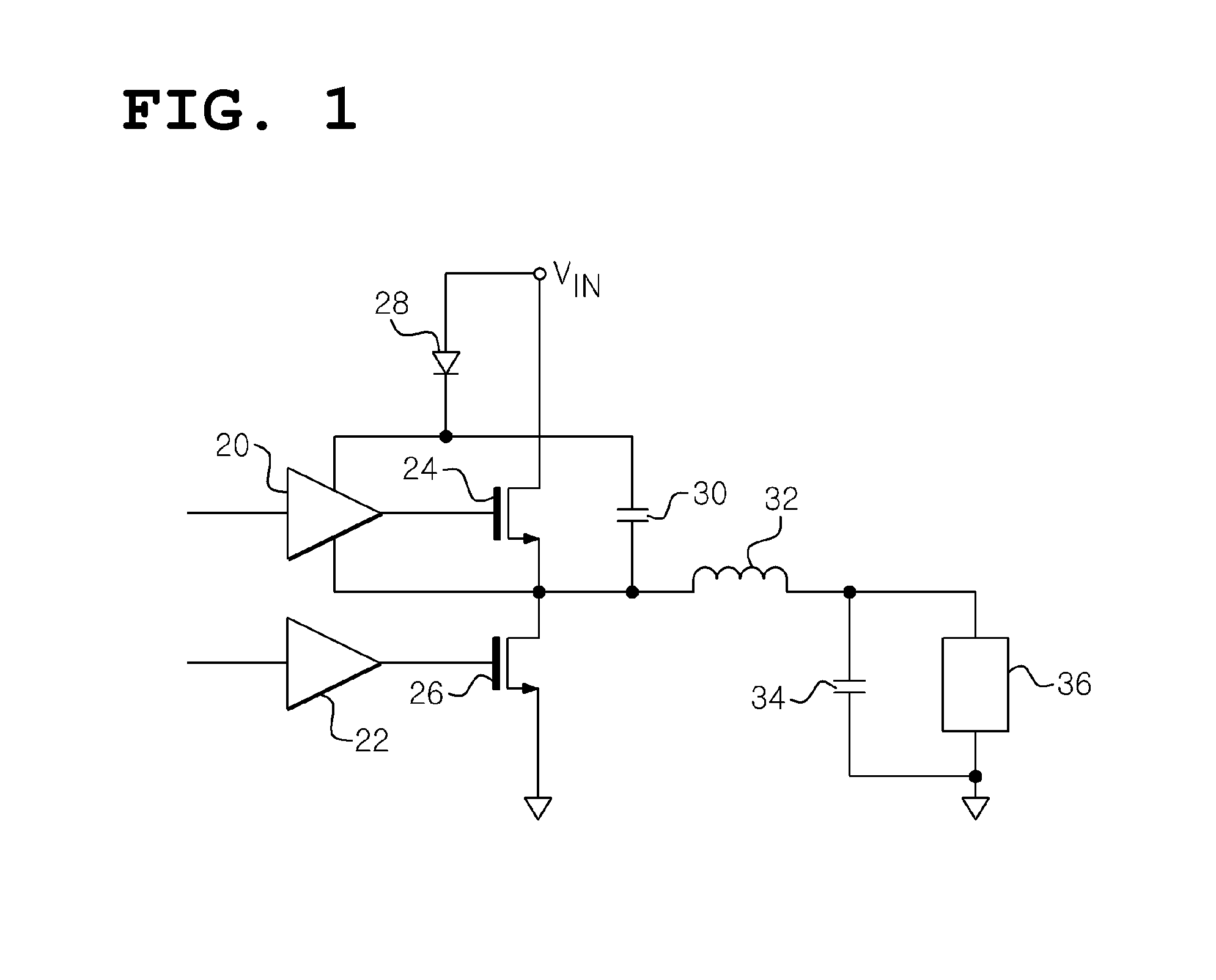
However, although a PMOS output device has higher performance than an NMOS device, the PMOS output device is disadvantageous in that the cost thereof is higher than the NMOS device.
The conventional technology is disadvantageous in that the converter should keep the duty cycle lower than the 100% duty cycle in order to recharge the bootstrap capacitor.
Accordingly, when the 100% duty cycle is required because the input supply voltage drops, a problem arises in that some components cannot operate.
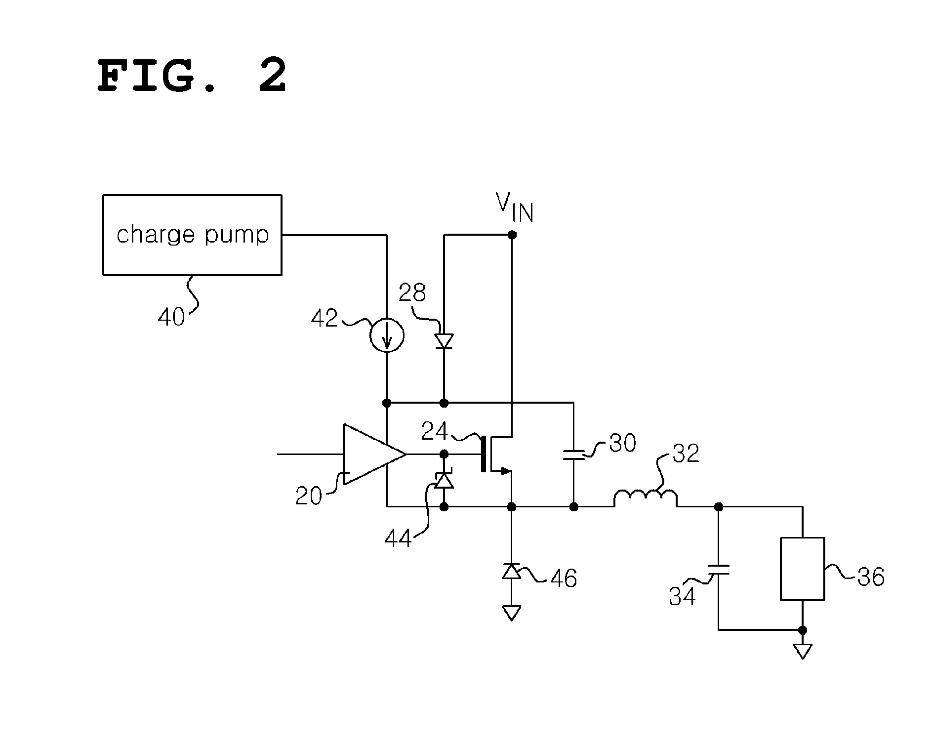
However, the high-power charge pump is disadvantageous in that it is very expensive in the silicon region (or on a silicon basis), has very high cost because additional external capacitors are used, and is subject to many external influences.
Furthermore, since the conventional technology using a high-power charge pump is designed to allow the amount of charge transferred from the charge pump to be large, the gate voltage of the high-side switch may increase to a voltage above a required voltage, with the result that there is a strong possibility of the high-side switching element being damaged.
However, the process utilizing a Zener diode is provided by only limited vendor, the prices of products utilizing a Zener diode increase.
In particular, in the case of products applied to vehicles or automotives, the choice of process is more limited if one wants to use a Zener diode in an IC chip.

Method used


Image

  • Switching mode converter and method for controlling thereof
  • Switching mode converter and method for controlling thereof
  • Switching mode converter and method for controlling thereof

Examples


Embodiment Construction

[0058]The terms used herein are used merely to describe specific embodiments, but are not intended to limit the present invention. The singular expressions include plural expressions unless explicitly stated otherwise in the context thereof. It should be appreciated that in this application, the use of the terms “include(s),”“comprise(s)”, “including” and “comprising” is intended to denote the presence of the characteristics, numbers, steps, operations, elements, or components described herein, or combinations thereof, but is not intended to exclude the probability of presence or addition of one or more other characteristics, numbers, steps, operations, elements, components, or combinations thereof.

[0059]Unless defined otherwise, all terms used herein, including technical terms or scientific terms, have the same meanings as those generally understood by persons of ordinary skill in the technical field to which the present invention pertains. The terms, such as terms that are general...


PUM


Abstract

Disclosed herein are a switching mode converter and a method for controlling thereof. The switching mode converter includes a switching element, a bootstrap capacitor, and a control unit. The switching element is connected between one side of a first semiconductor device, another side of the first semiconductor device is connected to a ground, and an input power. The bootstrap capacitor is configured such that one side of the bootstrap capacitor is connected to the one side of the first semiconductor device. The control unit controls the output current or output voltage of a common charge pump provided to the switching element and the bootstrap capacitor in order to control the charging state of the bootstrap capacitor and the gate voltage of the switching element.

Description

CROSS-REFERENCE TO RELATED APPLICATION[0001]This application claims under 35 U.S.C. §119(a) the benefit of Korean Applications No. 10-2012-0098398 filed on Sep. 5, 2012, No. 10-2012-0098402 filed on Sep. 5, 2012, and No. 10-2012-0098406 filed on Sep. 5, 2012, which applications are incorporated herein by reference.TECHNICAL FIELD[0002]The present invention relates, in general, to a switching mode converter and, more particularly, to a switching mode converter capable of allowing a System on Chip (SoC) to be implemented and safely providing a bootstrap function, a switching mode converter capable of providing stable 100% duty cycle mode, and a switching mode converter capable of preventing an excessive voltage from being applied to the gate of a switching element because of charges transferred from a charge pump. Furthermore, the present invention relates to a method of controlling the switching mode converters.BACKGROUND ART[0003]Conventional buck mode (switching mode) converters us...

Claims


Application Information

Patent Timeline
Patent Type & Authority Applications(United States)
IPC IPC(8): G05F3/02
CPCG05F3/02H02M1/36H02M3/1588Y02B70/10H02M3/1582H02M3/1584
Inventor QU, WANYUANWOO, YOUNG JINJEON, JIN YONGHAN, DAE KEUNSON, YOUNG SUK
Owner SILICON WORKS CO LTD
Learn More