Network management apparatus, network management method, and network management system
a network management and network management technology, applied in the field of network management apparatus, network management method, network management system, to achieve the effect of improving network use efficiency
- Summary
- Abstract
- Description
- Claims
- Application Information
AI Technical Summary
Benefits of technology
Problems solved by technology
Method used
Image
Examples
first embodiment
(1) First Embodiment
(1-1) Configuration of Network Management System
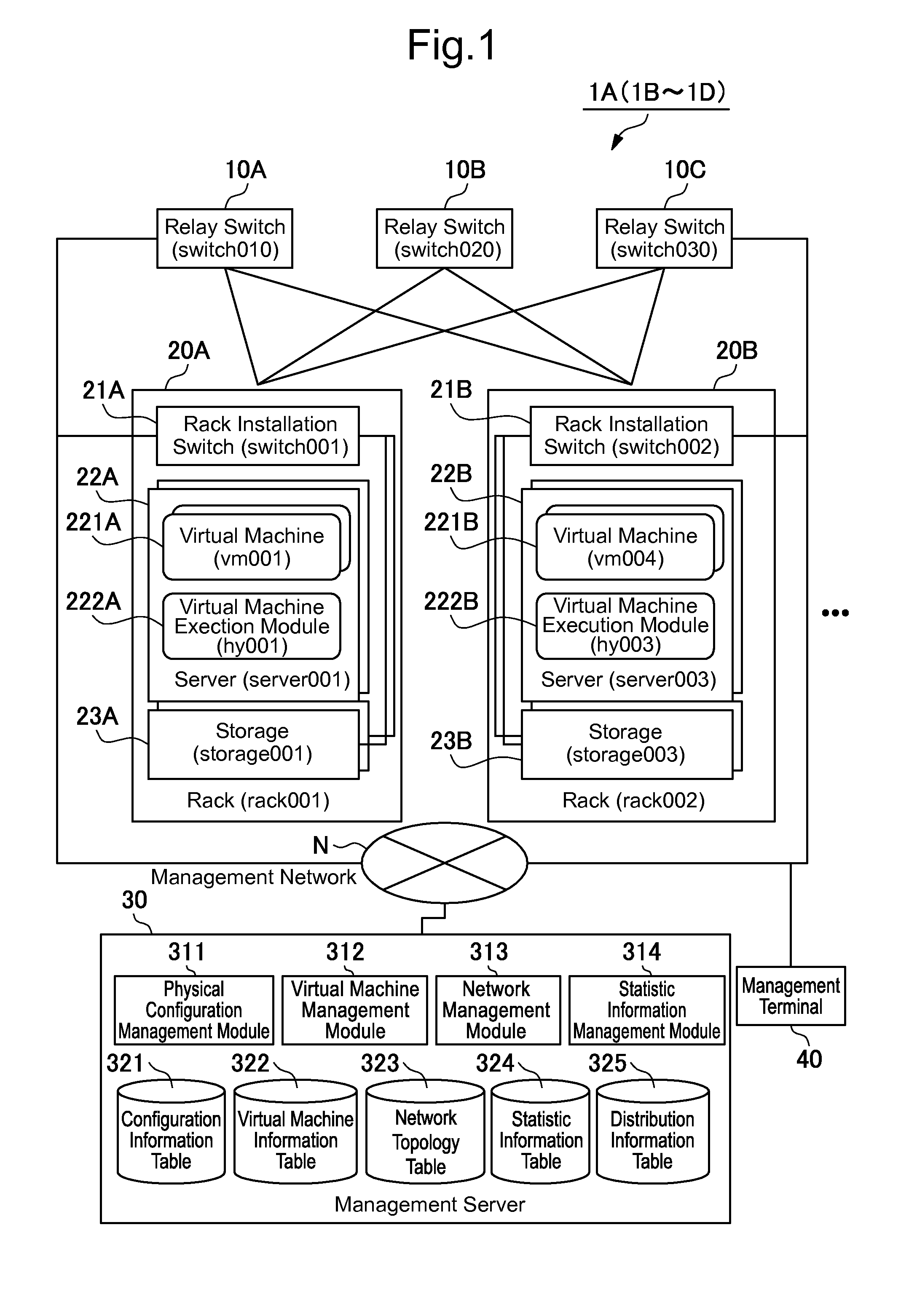
[0036]FIG. 1 illustrates a schematic logical configuration of a network management system1A. This network management system 1A includes relay switches 10A to 100, racks 20A and 20B, a management server 30, and a management terminal 40.
[0037]Incidentally, this network management system 1A comprises three relay switches 10A to 10C, two racks 20A and 20B, one management server 30, and one management terminal 40; however, the number of such elements according to the present invention is not limited to this example. Moreover, if the relay switches are not particularly distinguished one from another in the following explanation, they will be described as the “relay switch 10”; and if the racks 20A and 20B are not particularly distinguished one from the other, they will be described as the “rack 20.”
[0038]The relay switches 10A to 10C are transfer switches for transferring packets when the packets are transferred between t...
second embodiment
(2) Second Embodiment
(2-1) Configuration of Network Management System
[0162]Referring to FIG. 1, reference numeral 1B represents a network management system 1B according to a second embodiment as a whole. This network management system 1B is configured in the same manner as the network management system 1A according to the first embodiment, except that a new MAC address can be assigned, even when adding a new virtual machine, in order to balance the load on the network and that the management server 30 includes the virtual machine operation information table 326.
[0163]Incidentally, if the communication property of the virtual machine to be newly added, including its communication target and traffic volume, is not known at all in advance, it is generally difficult to assign a new MAC address to the virtual machine to be newly added in order to balance the load on the network. However, if the communication property of the virtual machine to be newly added can be estimated in advance, i...
third embodiment
(3) Third Embodiment
(3-1) Configuration of Network Management System
[0189]Referring to FIG. 1, reference numeral 1C represents network management system 1C according to a third embodiment as a whole. This network management system 1C is configured in the same manner as the network management system 1A according to the first embodiment, except that the network use efficiency can be improved by distributing communication flows to as many as the number of ECMPs and transferring them in an environment where no guarantee for the packet transfer order is required (hereinafter referred to as the “communication requirement mixed environment”).
[0190]Specifically speaking, the aforementioned first embodiment is premised on the environment where packets are sorted to ECMPs on a flow basis in order to guarantee the packet transfer order of communication flows; and realizes a path change on the flow basis by changing the address of the virtual machine 221. However, with a general network managem...
PUM
 Abstract
Description
Claims
Application Information
 - R&D
- Intellectual Property
- Life Sciences
- Materials
- Tech Scout
- Unparalleled Data Quality
- Higher Quality Content
- 60% Fewer Hallucinations
Browse by: Latest US Patents, China's latest patents, Technical Efficacy Thesaurus, Application Domain, Technology Topic, Popular Technical Reports.
© 2025 PatSnap. All rights reserved.Legal|Privacy policy|Modern Slavery Act Transparency Statement|Sitemap|About US| Contact US: help@patsnap.com


