
Hybrid fiber optic cable systems

a fiber optic cable and hybrid technology, applied in the direction of fibre mechanical structures, cables, instruments, etc., can solve the problems of inefficiency of connectorized cables including optical fibers and electrical conductors, and the hybrid cable is either too stiff or susceptible to breakage problems. , to achieve the effect of reducing impedance variations, reducing costs, and reducing attenuation during bending

Active Publication Date: 2014-03-06
CORNING OPTICAL COMM LLC
View PDF4 Cites 8 Cited by
  • Summary
  • Abstract
  • Description
  • Claims
  • Application Information

AI Technical Summary

Benefits of technology

The patent text describes a new type of fiber optic cable that includes both electrical and optical components. This hybrid cable design allows the optical fibers to move around and control how the cable bends, which reduces signal loss when the cable is bent. The cable also has a channel that allows for movement of the optical fibers. The hybrid cable can connect to optical devices and also has a connector that allows for a more efficient connection to the devices. Overall, this new design helps to reduce costs and improve performance.

Problems solved by technology

In either case, incrementally adding more optical fibers and / or electrical conductors in a hybrid cable can cause issues.
Providing additional optical fibers and / or electrical conductors in a cable jacket that may be required to maintain a small outer diameter (such as for portable devices) may collectively cause the hybrid cable to either be too stiff or susceptible to breakage issues.
Further, the optical fibers in the hybrid may also be subjected to severe bends, including pinch bends, when the optical fibers are bent.
Further, connectorized cables including optical fibers and electrical conductors may not be efficient.
The inefficiency occurs because of interference factors, for example, stray capacitance, which causes the impedance of connectorized systems to vary from ideal.
Traditional methods of controlling impedance by merely insulating each separate electrical conductor subassembly may result in hybrid fiber optic cables that are too stiff and / or too thick to easily use, store, and / or transport and thereby may be inadequate for mobile use.

Method used


Image

  • Hybrid fiber optic cable systems
  • Hybrid fiber optic cable systems
  • Hybrid fiber optic cable systems

Examples


Embodiment Construction

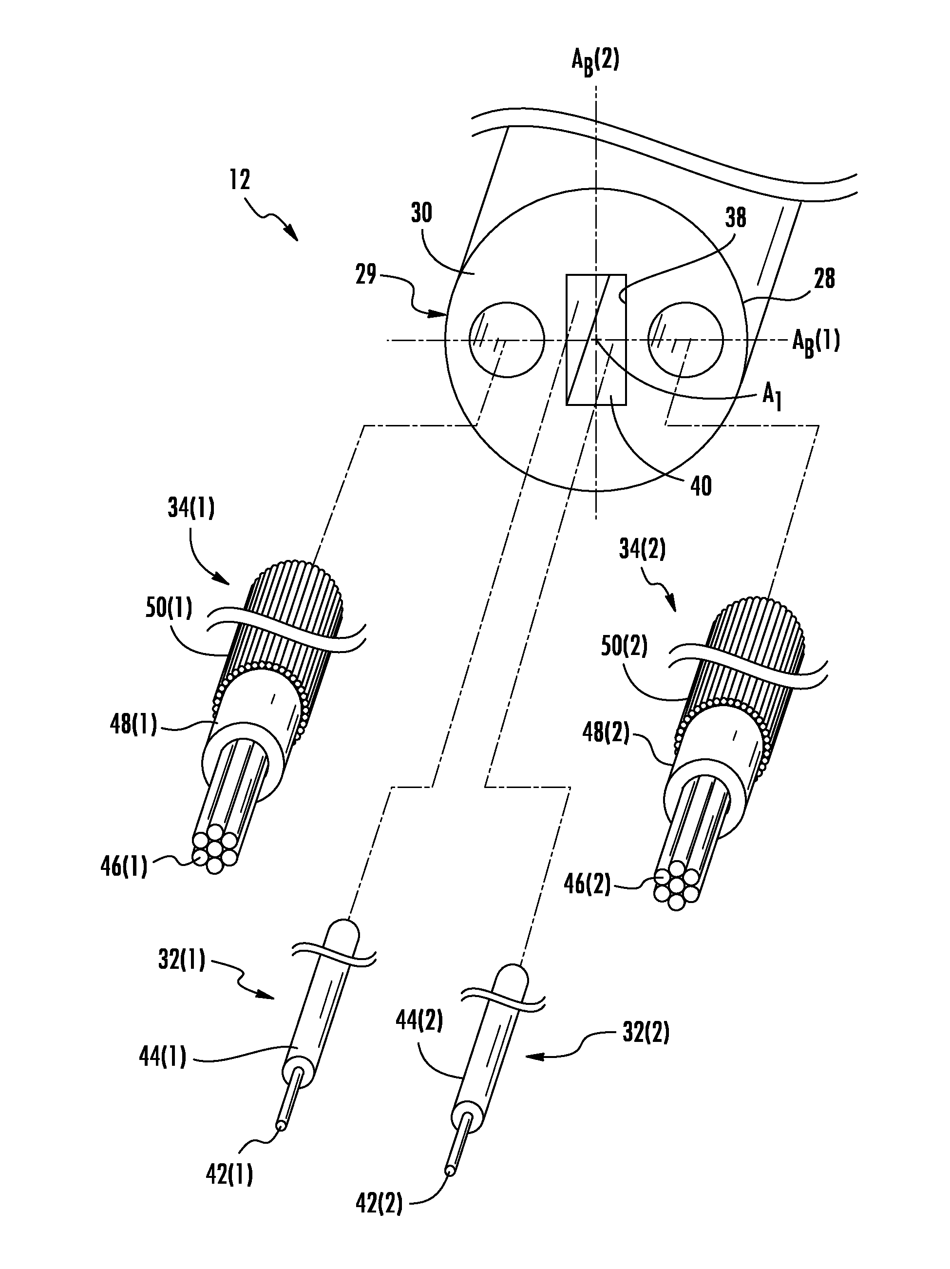
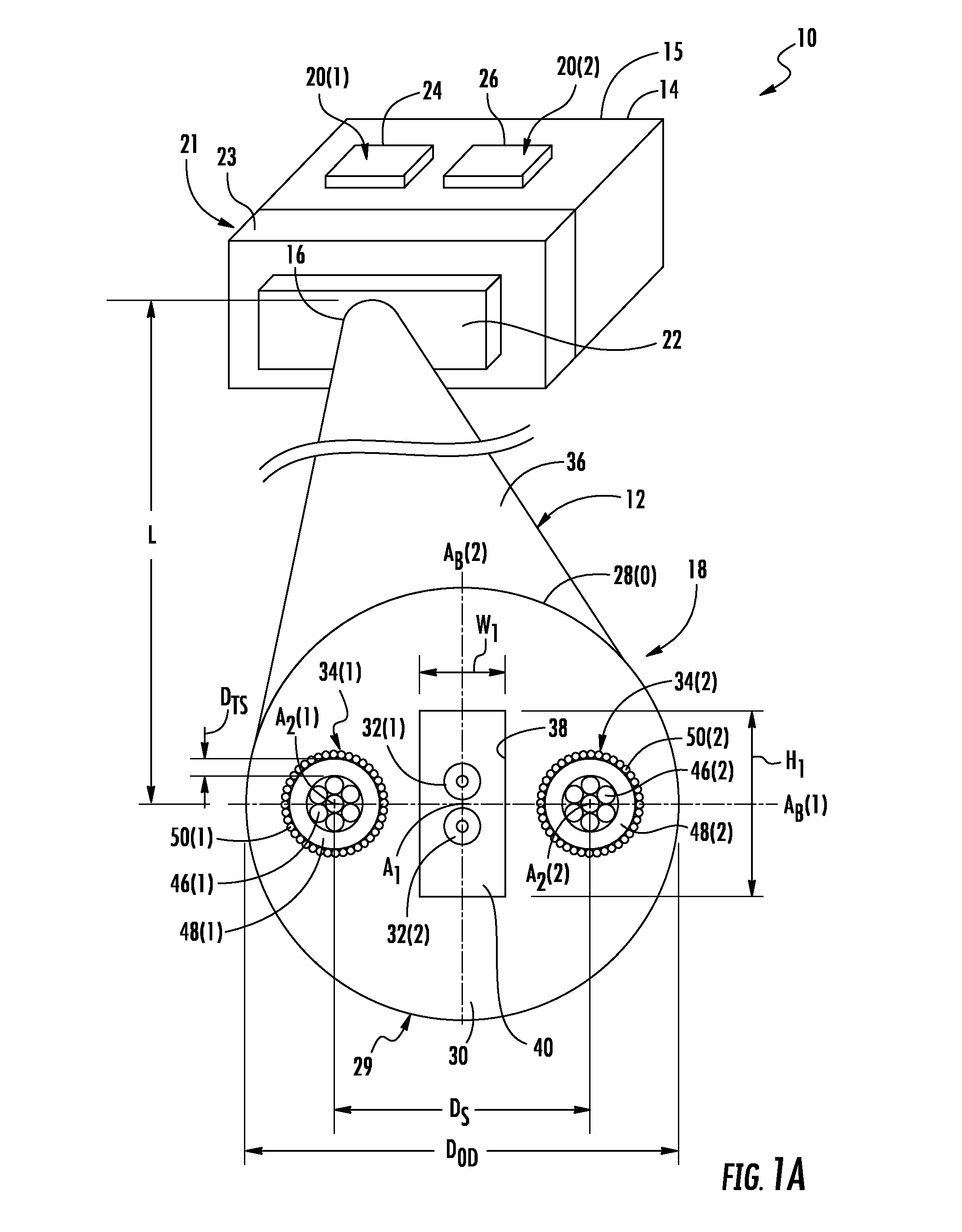
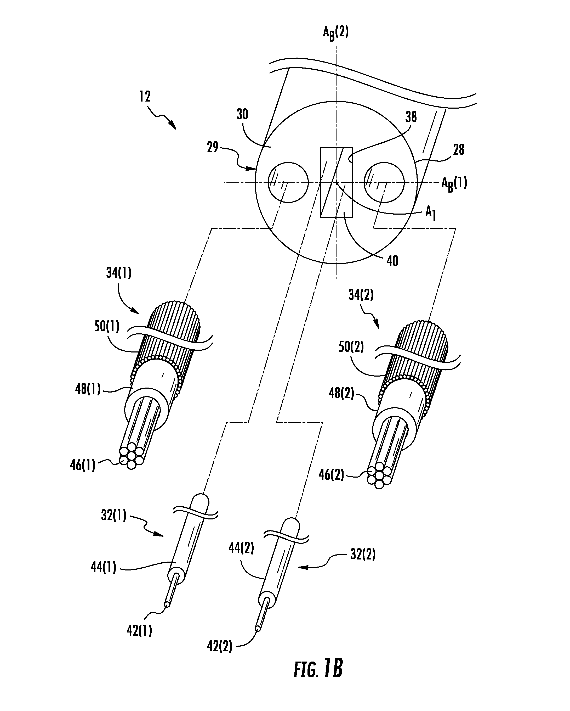
[0008]Embodiments disclosed herein include hybrid fiber optic cables including one or more electrical coaxial subassembly allowing for fiber movement to reduce attenuation during bending. Related connectorized cables and systems are also disclosed. The hybrid fiber optic cables include both one or more coaxial subassembly and optical fibers to provide both optical and electrical connectivity as part of a connectorized system. Use of one or more coaxial subassembly reduces impedance variations and lowers cost. Each coaxial sub-assembly also includes multiple electrical conductors to increase electrical connectivity capacity (e.g., power and signals) of the hybrid cable, as needed or desired. Further, the hybrid cable may include a channel with one or more optical fibers of the hybrid cable disposed therein, free of attachment to the channel. The channel allows the optical fibers to move relative to the cable jacket and control bend radius to reduce optical attenuation when the hybrid...


PUM


Abstract

Hybrid fiber optic cables including one or more electrical coaxial subassembly allowing for fiber movement to reduce attenuation during bending are disclosed. Related connectorized cables and systems are also disclosed. The hybrid fiber optic cables include both one or more coaxial subassembly and optical fibers to provide both optical and electrical connectivity as part of a connectorized system. Use of one or more coaxial subassembly reduces impedance variations and lowers cost. Each coaxial sub-assembly also includes multiple electrical conductors to increase electrical connectivity capacity (e.g., power and signals) of the hybrid cable, as needed or desired. Further, the hybrid cable may include a channel with optical fiber(s) of the hybrid cable disposed therein, free of attachment to the channel. The channel allows the optical fibers to move relative to the cable jacket and control bend radius to reduce optical attenuation when the hybrid fiber optic cable is bent.

Description

BACKGROUND[0001]1. Field of the Disclosure[0002]Technology of the disclosure relates to hybrid fiber optic cables, in some cases, comprising multiple optical fibers and electrical conductors disposed in a cable jacket to support optical and electrical connections.[0003]2. Technical Background[0004]Benefits of optical fibers include extremely wide bandwidth and low noise operation. In applications where high bandwidth and electrical conductor interconnectivity is desired, hybrid fiber optic cables may be employed. Hybrid fiber optic cables include one or more optical fibers capable of transporting signals optically at high bandwidths. Hybrid cables also include one or more electrical conductors capable of carrying electrical energy, such as signals and / or power as an example. These hybrid cables may be employed in devices, such as user devices, to provide optical and electrical signal connectivity.[0005]Device manufacturers and users of these devices may continue to provide applicati...

Claims


Application Information

Patent Timeline
IPC IPC(8): G02B6/44
CPCG02B6/4416G02B6/3817G02B6/4401G02B6/443H01B11/22
Inventor REGISTER, III, JAMES ARTHURMCCOLLOUGH, WILLIAM WELCH
Owner CORNING OPTICAL COMM LLC
Learn More