Bass drum

Active Publication Date: 2014-03-13
YAMAHA CORP
View PDF27 Cites 18 Cited by
  • Summary
  • Abstract
  • Description
  • Claims
  • Application Information

AI Technical Summary

Benefits of technology

[0020]The bass drum having this feature can reduce internal resonance generated inside the shell. In this case, by providing the sound-absorbing member on the inner peripheral surface of the shell, the bass drum can reduce only the internal resonance generated inside the shell without a decrease in vibrations of the drumhead. This featur

Problems solved by technology

As for the above-described drum having the vibration-absorbing member, however, because the vibration-absorbing member is attached to the entire surface of the drumhead, impaired movability of the drumhead increases to result in muffled sounds.
In a case where the entire surface of the vibration-absorbing member made of a rubber sheet is fixed

Method used


Image

  • Bass drum
  • Bass drum
  • Bass drum

Examples


first embodiment

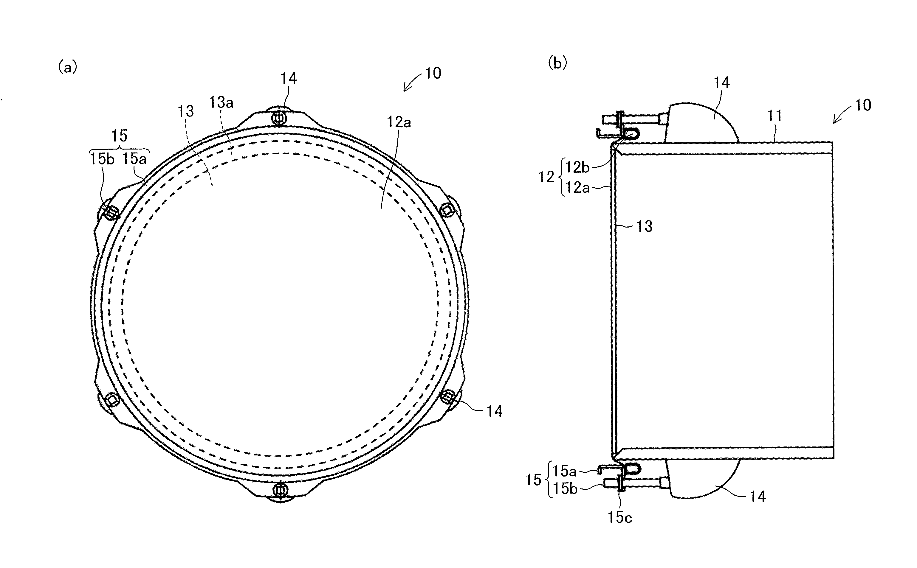
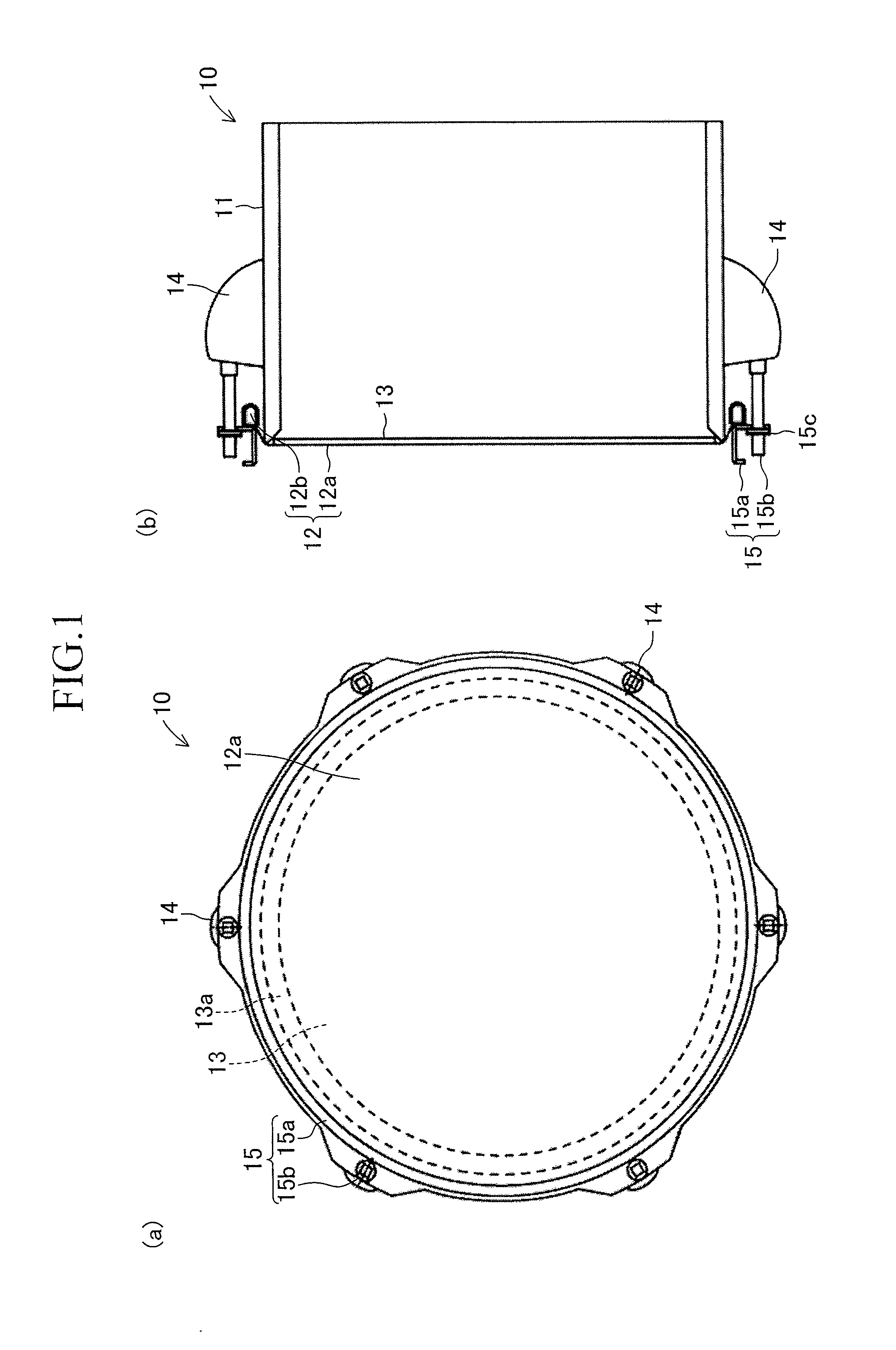
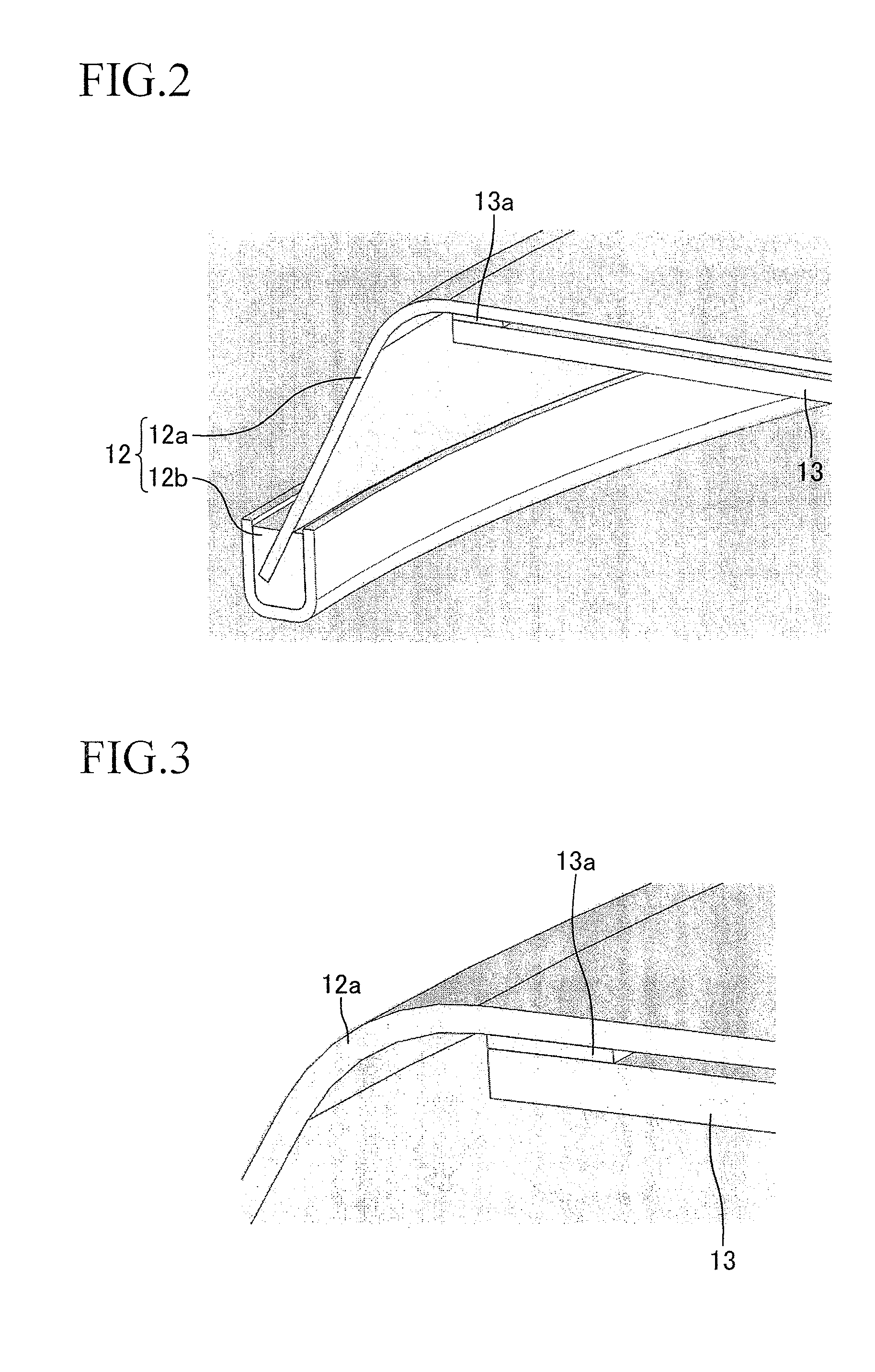
[0042]A bass drum according to the first embodiment of the present invention will now be described with reference to the drawings. FIGS. 1 (a) and (b) show a bass drum 10 according to the embodiment. In the following explanation on the bass drum 10, the side facing audience is defined as the front (forward), while the side facing a player of the bass drum is defined as the back (rear). The bass drum 10 is designed to have a diameter of 12 inches with a depth of 11 inches. The bass drum 10 has a hollow cylindrical shell 11 which is a drum shell, and a circular drumhead 12 mounted on the rear opening end of the shell 11. To the reverse side (inner surface) of the drumhead 12, furthermore, a striking surface attachment 13 (a struck head mass-adding member 13) is attached. Basically, the mass of the striking surface attachment 13 reduces volume of sounds generated by the bass drum 10 by suppressing vibrations of the drum head 12.

[0043]The shell 11 is made of wood (birch), and has functi...

second embodiment

[0068]FIGS. 10(a) to (c) indicate a bass drum 20 according to the second embodiment of the present invention. The bass drum 20 has a hollow cylindrical shell 21 which is a drum shell, a circular drumhead 22 mounted on the rear opening end of the shell 21, and a circular front head 26 mounted on the front opening end of the shell 21. The drumhead 22 is formed of a head portion 22a and a flesh hoop 22b. To the reverse side of the head portion 22a, a striking surface attachment 23 is attached with a double-faced tape 23a. The drumhead 22 is mounted on the rear opening end of the shell 21 with six lugs 24 provided on an outer peripheral surface of the shell 21 and a stretching portion 25 formed of a hoop 25a including engaging protrusions 25c and tuning pins 25b.

[0069]Among the above-described members, the shell 21, the drumhead 22, the striking surface attachment 23, the double-faced tape 23a, the lugs 24 and the stretching portion 25 are configured similarly to the shell 11, the drum...

third embodiment

[0072]FIGS. 11(a) to (c) indicate a bass drum 30 according to the third embodiment of the present invention. The bass drum 30 is designed such that a head portion 36a of a front head 36 has an air hole 36b which is an air vent according to the present invention. The air hole 36b is provided so that the air hole 36b will be away from the center of the head portion 36a by 56 mm, and will have a diameter of 100 mm. Except the air hole 36b, the bass drum 30 is configured similarly to the above-described bass drum 20. Therefore, similar components are given similar numerals to omit explanations of the components.

[0073]Because of the air hole 36b provided on the head portion 36a, the bass drum 30 allows the air within the shell to escape to the outside to speed up decay of struck sounds. As a result, the bass drum 30 can generate tighter sounds than struck sounds generated by the bass drum 20. The operational advantage of the bass drum 30 other than the above is the same as that of the ba...


PUM


Abstract

A bass drum 10 has a hollow cylindrical shell 11, a drumhead 12 mounted on an opening end of the shell 11 to form a striking surface, and a striking surface attachment 13 provided on the reverse side of the drumhead 12. The striking surface attachment 13 is formed of an elastic sheet. At least a part of an outer area of the striking surface attachment 13 is fixed to the drumhead 12 and a central area of the striking surface attachment 13 is not fixed to the drumhead 12. As a result, the bass drum 10 can generate a struck sound having both deep bass sound and clear attack.

Description

BACKGROUND OF THE INVENTION[0001]1. Field of the Invention[0002]The present invention relates to improvement in sound quality of a bass drum.[0003]2. Description of the Related Art[0004]A bass drum is played along with a tom-tom and a snare drum as a drum kit. For bass drum sounds, both powerful deep bass sound and attack sound brought about by a beater are needed. In order to get powerful deep bass sound, larger bass drums are used, or gel or a sponge ring are attached on a drumhead to emphasize deep bass sound. Such bass drums include a bass drum which has a vibration-absorbing member on a head member to vary bass drum sounds (for example, see Japanese Registered Utility Model No. 3004768). This drum is designed such that a drumhead is mounted on one opening end of a drum shell through a drum hoop while a vibration-absorbing member made of a thin rubber sheet or plastic is attached to the reverse side of the drumhead which is a striking surface.SUMMARY OF THE INVENTION[0005]As for...

Claims


Application Information

Patent Timeline
IPC IPC(8): G10D13/02G10D13/20G10D13/22
CPCG10D13/027G10D13/02G10D13/26G10D13/14G10D13/20G10D13/16G10D13/22
Inventor HASHIMOTO, RYUJI
Owner YAMAHA CORP
Why Eureka
Try Eureka