System, transition conduit, and article of manufacture for transitioning a fluid flow

a technology of fluid flow and transition system, applied in the direction of machines/engines, mechanical equipment, pipe elements, etc., can solve the problems of reducing saving valuable engine space, so as to reduce the likelihood of undesirable flow disturbance, improve the mixing of secondary flow, and save valuable engine space

Active Publication Date: 2014-03-13
GE GLOBAL SOURCING LLC
View PDF6 Cites 6 Cited by
  • Summary
  • Abstract
  • Description
  • Claims
  • Application Information

AI Technical Summary

Benefits of technology

[0006]The volute passageway includes a slot that follows a route around the curving volute passageway and opens into an interior of the main conduit, with the slot defined at least in part by a lip. The slot establishes a slot entry/exit path (aperture path) for a secondary fluid flow to enter the main conduit upstream of the second turbine. By introducing the secondary fluid flow into the main conduit in this manner, such a configuration e...

Problems solved by technology

Such a configuration also decreases the likelihood of undesirable flow disturbances within the main fl...

Method used


Image

  • System, transition conduit, and article of manufacture for transitioning a fluid flow
  • System, transition conduit, and article of manufacture for transitioning a fluid flow
  • System, transition conduit, and article of manufacture for transitioning a fluid flow

Examples


Embodiment Construction

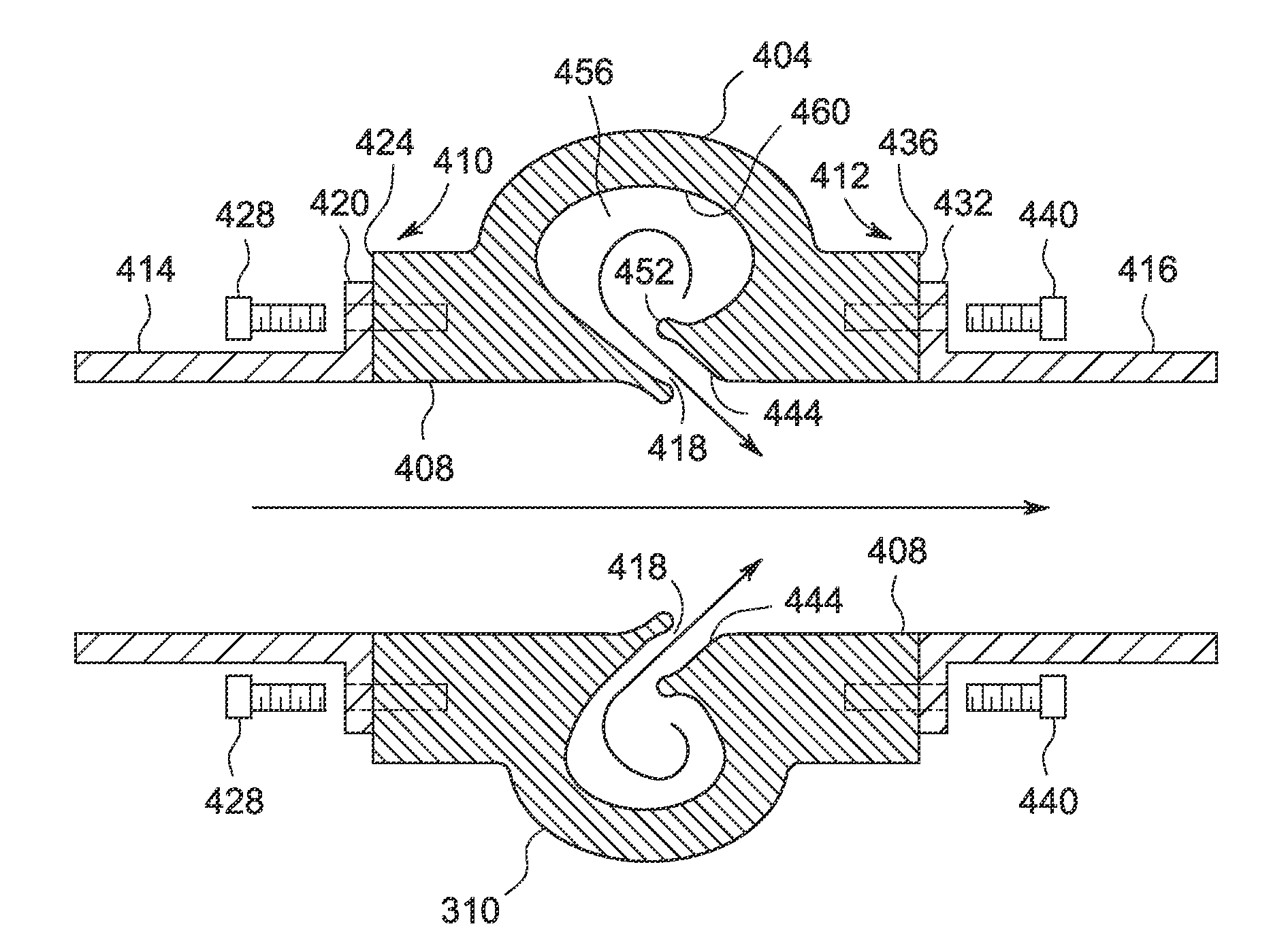
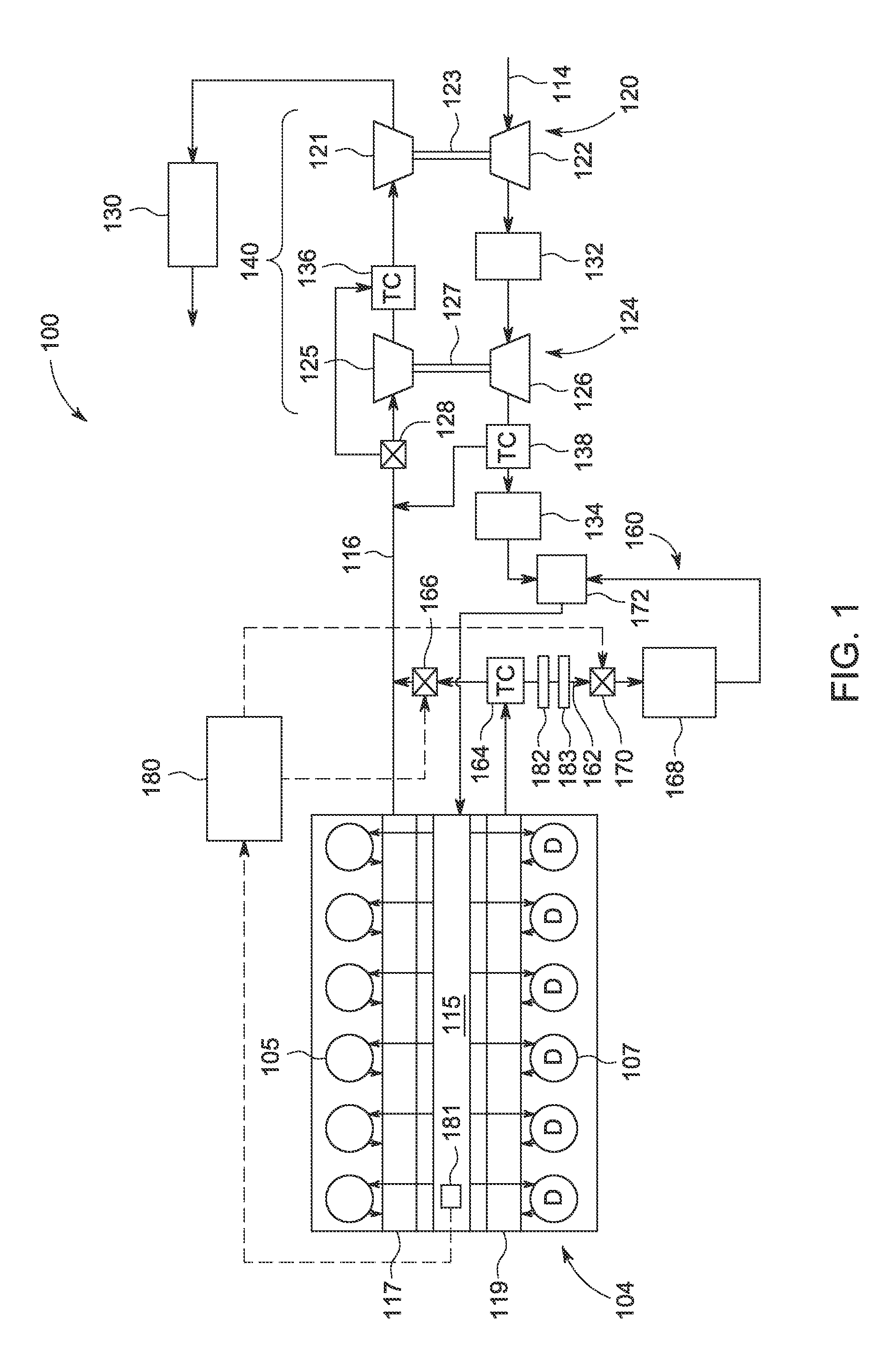
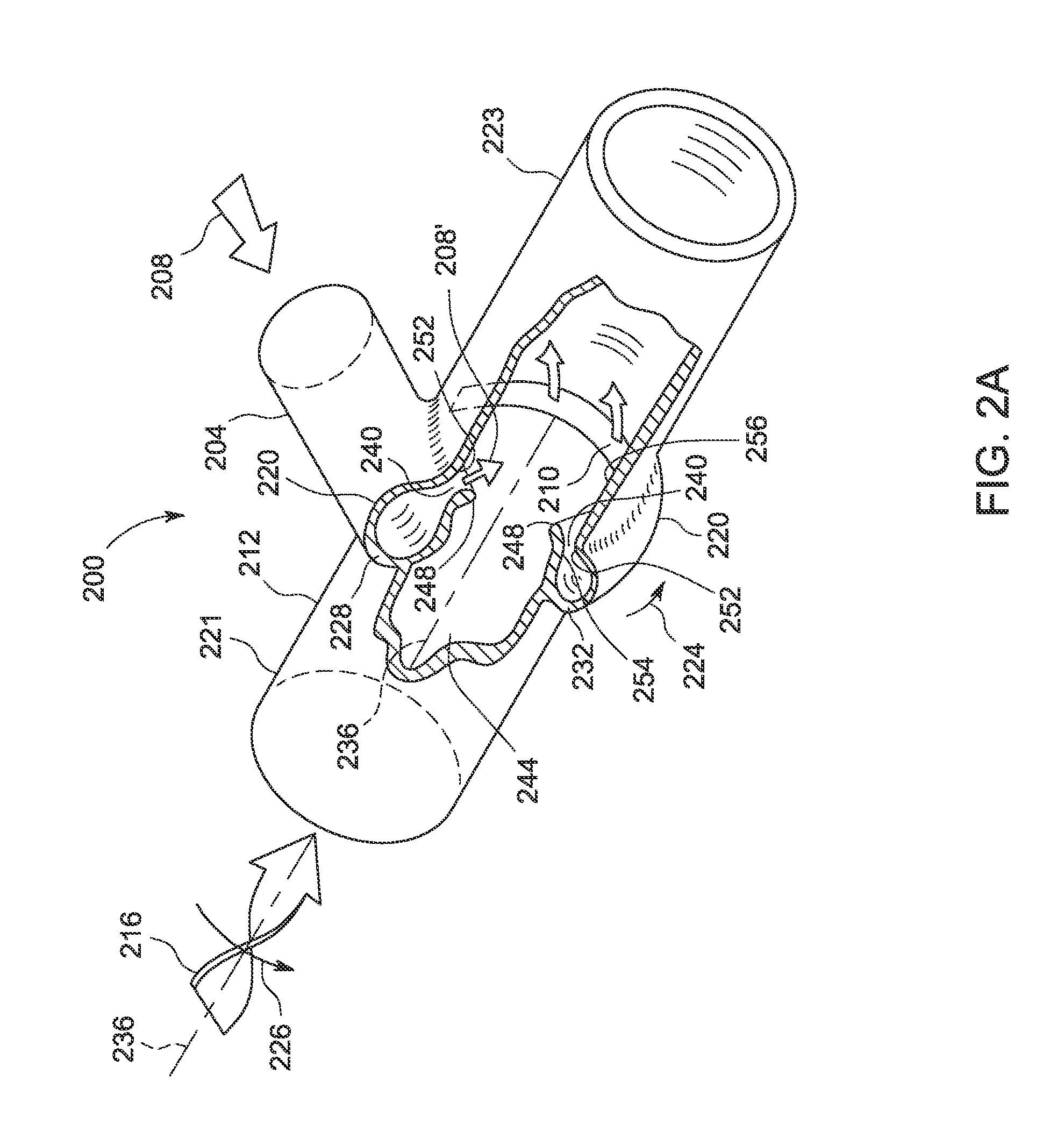
[0016]The following description relates to various embodiments of a system for transferring fluid flow within an engine and related apparatuses and articles of manufacture. In some embodiments, the system is configured for an engine in a vehicle, such as a rail vehicle. In other embodiments other vehicles may be used. FIG. 1 shows a schematic diagram of an example engine system in which the fluid transfer system of the present disclosure may be utilized. FIG. 2A shows a cut away view of an embodiment of a transition conduit coupled with a main conduit and including a volute passageway with a slot that may be used in the engine of FIG. 1. In this configuration the transition conduit may be used to deliver a secondary flow to the main conduit. FIG. 2B shows a detailed view of a cutaway location of the transition conduit of FIG. 2A. FIG. 3 shows the transition conduit coupled with a main conduit of FIG. 2A in a configuration that may be used to extract fluid flow from the main conduit....


PUM


Abstract

Various systems and apparatuses are provided for a fluid transfer system for an engine. In one example, a system includes a first turbine having an exit for discharging a main fluid flow and a second turbine having an inlet for receiving at least a portion of the main fluid flow. A main conduit fluidically couples the exit of the first turbine to the inlet of the second turbine. A transition conduit is coupled with the main conduit and includes a volute passageway curving around the main conduit. The volute passageway includes a slot that follows a route around the curving volute passageway and opens into an interior of the main conduit. The slot is defined at least in part by a lip and establishes a path for either a secondary fluid flow to enter the main conduit or a portion of a main fluid flow to exit the main conduit.

Description

FIELD[0001]Embodiments of the invention relate to flow transition systems for an engine. Other embodiments relate to apparatuses and articles of manufacture for introducing a secondary fluid flow into a fluid carrier and / or extracting a portion of a main fluid flow from a fluid carrier.BACKGROUND[0002]Engine systems may include one or more turbochargers or other turbine-based systems. In some examples, turbocharger systems may include two turbochargers configured in series, such as a high pressure turbocharger fluidically coupled to a low pressure turbocharger. To control the boost pressure generated by the high pressure compressor, a bypass valve upstream from the high pressure turbine may be utilized to divert and bypass exhaust flow around the high pressure turbine. In one example, the diverted or bypass flow may be routed around the high pressure turbine and reintroduced into the exhaust flow downstream of the high pressure turbine and upstream from the low pressure turbine.[000...

Claims


Application Information

Patent Timeline
IPC IPC(8): F16L55/027
CPCF01N13/1811F01N13/1844F01N13/1872F02B37/013F15D1/02Y02T10/12
Inventor LORINGER, DANIEL EDWARDJOHNSON, LUKAS WILLIAMSWENSON, KENDALLERDMENGER, RODRIGO RODRIGUEZ
Owner GE GLOBAL SOURCING LLC
Why Eureka
Try Eureka