Automatic roller shade

a roller shade and automatic technology, applied in the field of roller shades, can solve the problems of inconvenience in use, small children's safety threats, and exposed pull cords and lifting cords of window shades, and achieve the effect of reducing the power consumption and manufacturing cost of automatic roller shades

Inactive Publication Date: 2014-03-13
CHICOLOGY
View PDF2 Cites 40 Cited by
  • Summary
  • Abstract
  • Description
  • Claims
  • Application Information

AI Technical Summary

Benefits of technology

[0005]A primary object of the present invention is to provide an automatic roller shade that has reduced power consumption and manufacturing cost while having a compact and esthetic appearance.
[0006]To achieve the above and other objects, the automatic roller shade according to the present invention has a structural design combining a first mounting bracket, a second mounting bracket, a shade body, a stop mechanism and a driving mechanism to overcome the problem of requiring a large-sized motor as found in the conventional automatic roller shades, and can therefore have the advantages of reduced power consumption, lowered manufacturing cost, and compact and esthetic appearance.
[0014]In the automatic roller shade of the present invention, the spiral spring element of the stop mechanism is connected to the winding element and accordingly to the roller of the shade body to unwind or rewind when the winding element and the roller rotate, and a nominal elastic rewinding force of the spiral spring element can be used to balance the force for lifting or rewinding the shade fabric and the gravitational force lowering or unwinding the shade fabric, so that the lifting of the shade fabric does not require a relatively large upward winding force and the shade fabric can stay at the selected height after it has been lifted or lowered. With the spiral spring element, the micro motor can be adopted as a power source of the driving mechanism to reduce the power consumption and manufacturing cost of the automatic roller shade. Further, the micro motor can be invisibly located in the roller of the shade body, allowing the whole roller shade to have a compact and esthetic appearance.

Problems solved by technology

The small child playing near the window shade is subject to the danger of being unexpectedly strangulated by the cords.
Therefore, the exposed pull cords and lifting cords of the window shades form a big potential threat to the safety of small children.
In addition, the cords of the lifting unit are also subject to tangling with one another to cause inconveniences in use.
The large-scale servo motor inevitably increases the manufacturing cost of the roller shade.
Further, the large-scale servo motor could not be invisibly mounted inside the head roller and is usually externally mounted to an end of the head roller, giving the whole roller shade a bulky and unpleasant appearance.

Method used


Image

  • Automatic roller shade
  • Automatic roller shade
  • Automatic roller shade

Examples


Embodiment Construction

[0022]The present invention will now be described with a preferred embodiment thereof and with reference to the accompanying drawings.

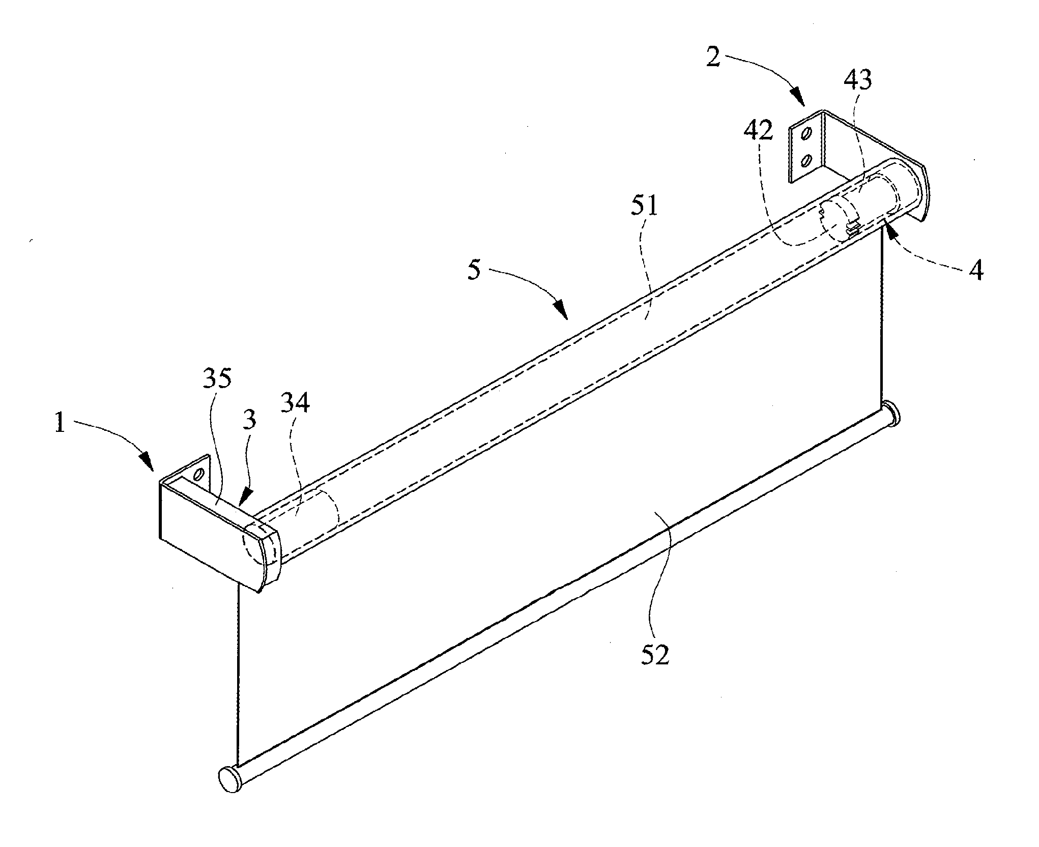
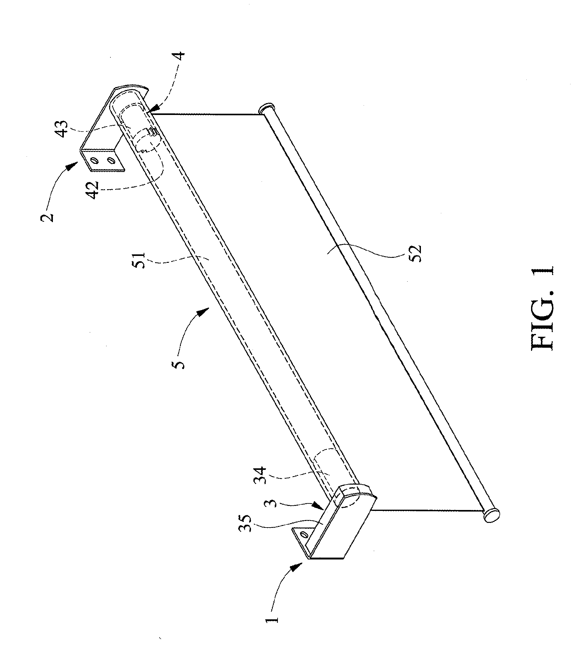
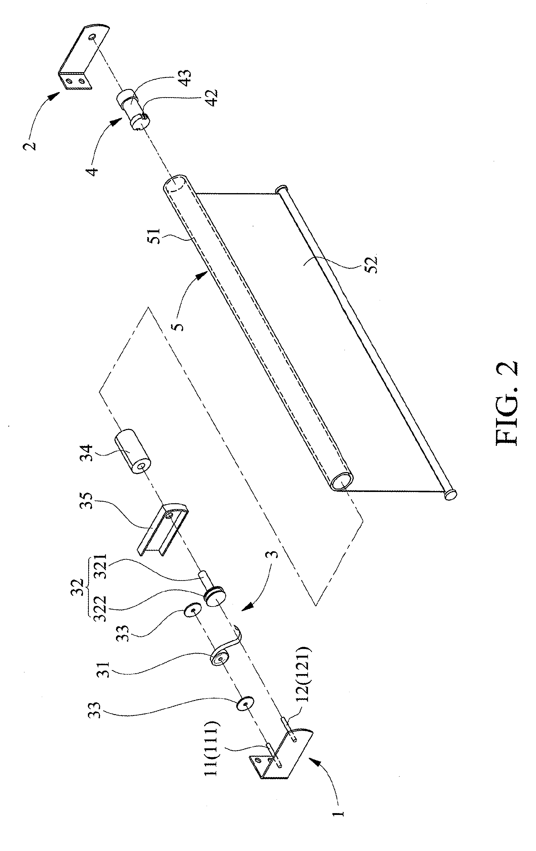
[0023]Please refer to FIGS. 1 and 2 that are assembled and exploded perspective views, respectively, of an automatic roller shade according to a preferred embodiment of the present invention. As shown, the automatic roller shade in the illustrated preferred embodiment includes a first mounting bracket 1, a second mounting bracket 2, a stop mechanism 3, a driving mechanism 4, and a shade body 5.

[0024]As can be seen in FIG. 2, the first mounting bracket 1 is a member to be fixedly mounted on a wall and is provided with a first supporting section 11 and a second supporting section 12 located adjacent to and spaced from the first supporting section 11. The first supporting section 11 has a first shaft 111 connected thereto, and the second supporting section 12 has a second shaft 121 connected thereto.

[0025]As also can be seen in FIG. 2, the second mountin...


PUM


Abstract

An automatic roller shade includes a shade body rotatably mounted to between a first and a second mounting bracket; a stop mechanism mounted in an end of a roller of the shade body; and a driving mechanism mounted in another opposite end of the roller. The stop mechanism includes a winding element connected to the roller and a spiral spring element having an end connected to the winding element. The spiral spring element enables a balance between a force for lifting or winding a shade fabric of the shade and the gravitational force lowering or unwinding the shade fabric. The driving mechanism at the other end of the roller can adopt a micro motor as a power source and the micro motor can be invisibly located inside the roller, enabling the automatic roller shade to have reduced power consumption and manufacturing cost while having a compact and esthetic appearance.

Description

FIELD OF THE INVENTION[0001]The present invention relates to a roller shade, and more particularly to an automatic roller shade, of which a shade fabric can be automatically wound and lifted or unwound and lowered.BACKGROUND OF THE INVENTION[0002]Many conventional window shades, such as the Roman shades, have a shade fabric that can be vertically lifted or lowered. These vertically operable window shades usually include a head rail, a lifting unit and a shade fabric connected to and hung from the head rail. The head rail is mounted to an upper edge of a window; the lifting unit includes a plurality of pull cords and lifting cords; and the shade fabric has an upper edge connected to the head rail and a lower edge controlled by the lifting unit to vertically move upward or downward. The pull cords and lifting cords are usually located at lateral sides of the window shade and can be easily accessed by a small child playing near the window shade. The small child playing near the window ...

Claims


Application Information

Patent Timeline
Patent Type & Authority Applications(United States)
IPC IPC(8): E06B9/68E06B9/72
CPCE06B9/42E06B9/50E06B9/72
Inventor CHEN, JU-HUAI
Owner CHICOLOGY
Why Eureka
Try Eureka