
Sheave block

a sheave block and sleeve technology, applied in the field of pulleys, can solve the problems of side plates or cheeks projecting from the sheave block, side plates or cheeks, and jeopardizing the proper operation of the sheave block, and achieve the effect of simple and inexpensive production and reduced overall dimensions

Inactive Publication Date: 2014-03-13
WINMAR RACING
View PDF2 Cites 7 Cited by
  • Summary
  • Abstract
  • Description
  • Claims
  • Application Information

AI Technical Summary

Benefits of technology

The present invention aims to solve the issue of requiring additional components to keep a sheave block stable and reduce its overall size. It provides a structure that is strong, compact, and easy to produce, eliminating the need for additional parts.

Problems solved by technology

The first solution entails risks of damage to the side plates or cheeks projecting from the sheave block both in the case of impact, which is anything but infrequent in particular on board racing clippers, and in the case where the pulley wheel over which the rope or sheet under load is run is not well aligned therewith.
Possible damage to the side plates or cheeks can jeopardize proper operation of the sheave block.
With the second solution the production of the sheave block is relatively complicated and burdensome on account of the need to make the internal ring of a number of components that must be assembled together: a central part, lateral annular shoulders, and the corresponding retention flanges.

Method used


Image

  • Sheave block
  • Sheave block
  • Sheave block

Examples


Embodiment Construction

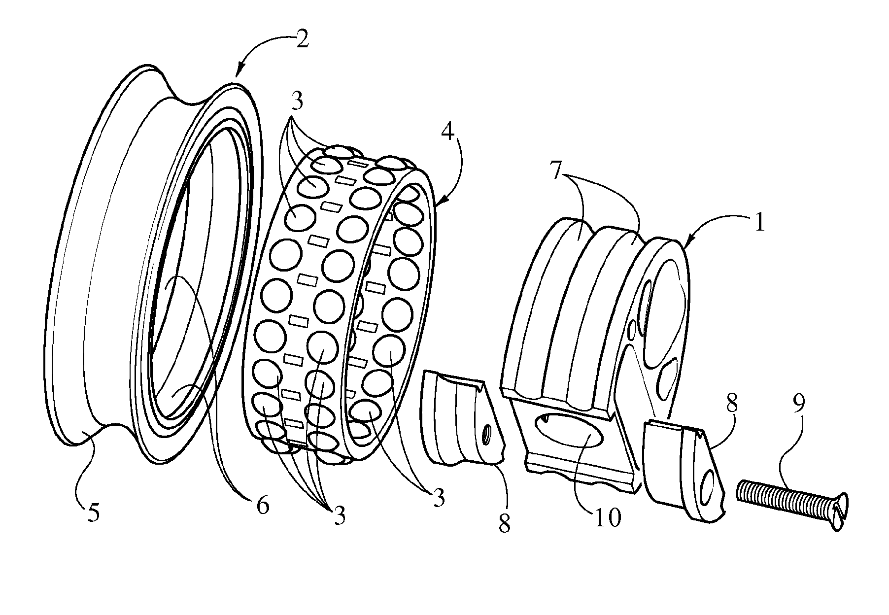
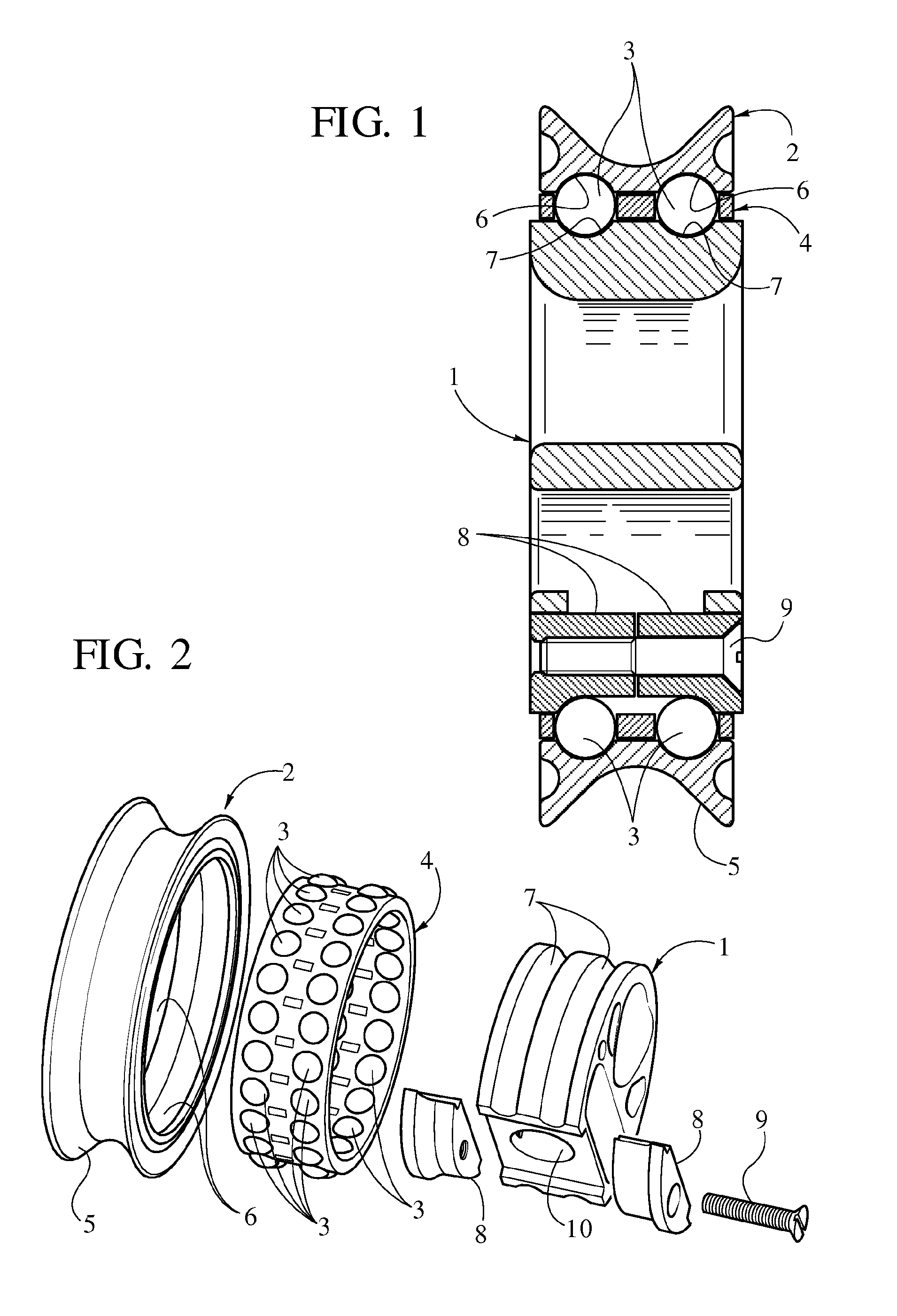
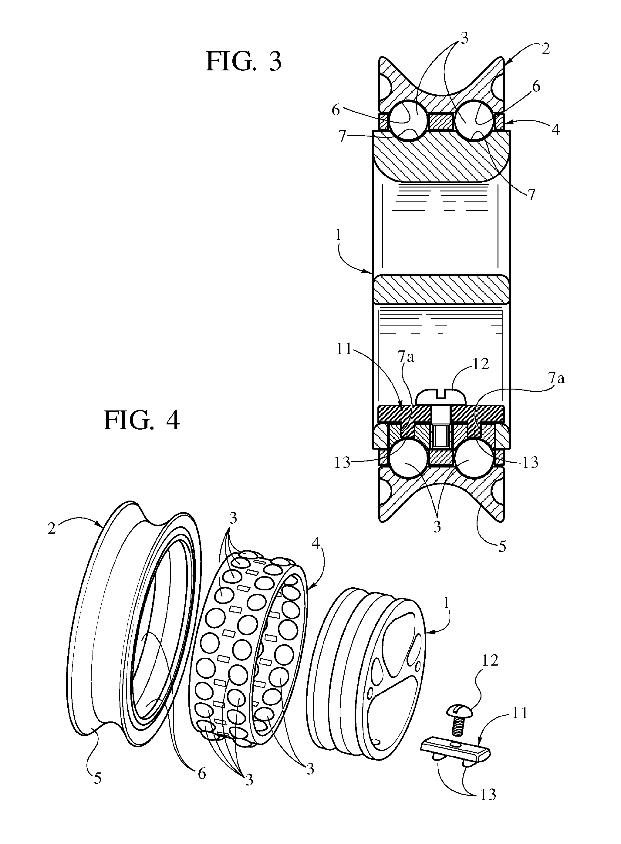
[0024]With initial reference to FIGS. 1. and 2, the sheave block according to a first embodiment of the invention comprises an internal ring 1, on which there turns coaxially a pulley wheel 2 with interposition of rolling members 3.

[0025]In this embodiment, as in the further embodiments that will be described hereinafter, the internal ring 1 and the pulley wheel 2, as well as the other components that will be described hereinafter, can be each made of a single piece, fur example a single piece of plastic material with high resistance, or else made of a number of materials and / or a number of parts rendered fixed with respect to one another during their production.

[0026]In the case of the example illustrated, the rolling members 3 are constituted by two annular series or rings of balls inserted within a common cage 4. It should be noted that in this as in the other embodiments described hereinafter the rolling members of the sheave block could be arranged according to a single annular...


PUM


Abstract

A sheave block includes an internal ring, an external pulley wheel, which turns coaxially on the internal ring, rolling means set between the ring and the pulley wheel, and means of mutual axial retention of the ring and of the pulley wheel. The means of mutual axial retention have mutually facing integral races of the ring and of the pulley wheel in radial-axial contact with the rolling means. The internal ring has at least one angular area of localized increase of the radial distance between the integral races, where there is applied an insert for restoring said radial distance.

Description

CROSS REFERENCE TO RELATED APPLICATIONS[0001]This application is a 371 National Phase of PCT International Application No. PCT / IB2012 / 051283 filed on Mar. 16, 2012, and published in English as WO 2012 / 127394 A1 on Sep. 27, 2012, which claims priority to Italian Patent Application No. TO2011A000240 filed on Mar. 18, 2011, the entire disclosures of which are incorporated herein by reference.FIELD OF THE INVENTION[0002]The present invention relates in general to pulleys of the type comprising an internal ring, an external pulley wheel that turns coaxially on the internal ring, and rolling means set between the ring and the pulley wheel.[0003]In particular, albeit not exclusively, the invention regards pulleys of this sort designed for use as sheave blocks on board watercraft, for running sheets or ropes subjected to heavy loads in restricted spaces. Fundamental requisites for said sheave blocks consist of a structure that is particularly sturdy but at the same time light and of limited...

Claims


Application Information

Patent Timeline
IPC IPC(8): B66D3/04
CPCB66D3/04F16C33/60F16C43/06
Inventor WIN, THIHADE MARI, SIMONE
Owner WINMAR RACING
Learn More