Display device and method of controlling display device

a display device and display device technology, applied in the field of display devices, can solve the problems of not being able to perform processing in response to the pointed location, not being able to perform processing on the input image itself based on the pointed location, and being connected to the devi

Active Publication Date: 2014-03-13
SEIKO EPSON CORP
View PDF5 Cites 18 Cited by
  • Summary
  • Abstract
  • Description
  • Claims
  • Application Information

AI Technical Summary

Benefits of technology

[0010]An advantage of some aspects of the invention is, in a configuration in which an input image is displayed by a display device, to perform processing on the input image in response to an operation with respect to a displayed image.

Problems solved by technology

In the configuration of Patent Document 1, the device that detects the pointed location of the pointer executes the operation in response to the pointed location, but the personal computer connected to the device is not able to perform an operation in response to the pointed location.
Accordingly, it has been impossible to perform processing in response to the pointed location with respect to the image itself input from the personal computer.
Therefore, in the case where the device that displays the input image detects the pointed location, processing on the input image itself based on the pointed location is not performed.

Method used


Image

  • Display device and method of controlling display device
  • Display device and method of controlling display device
  • Display device and method of controlling display device

Examples


Embodiment Construction

[0035]As below, an embodiment to which the invention is applied will be explained with reference to the drawings.

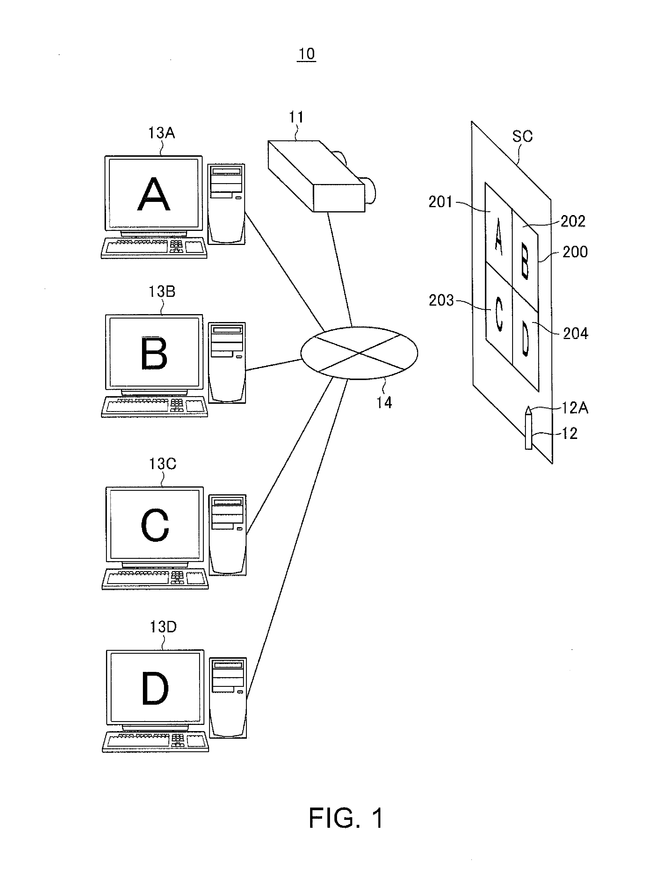
[0036]FIG. 1 shows a configuration of a projection system 1 using a projector 11 according to the embodiment. To the projector 11 as a display device, a plurality of PCs (personal computers) 13 as image supply devices are connected. In the embodiment, a configuration in which four PCs 13A to 13D are connected to the projector 11 via a network 14 will be explained, however, the number of PCs 13 is arbitrary. Further, the network 14 is formed by wired communication lines including LAN cables, for example, or wireless communication lines, and the projector 11 and the respective devices of the PCs 13A to 13D may mutually transmit and receive various data via the network 14.

[0037]The PCs 13A to 13D respectively supply image data to the projector 11 via the network 14, and the projector 11 projects images based on the image data input from the PCs 13A to 13D on a screen SC. The...


PUM


Abstract

A projector includes a projection unit that displays an image on a screen, a control unit that allows the projection unit to display a plurality of images based on image data input from a plurality of PCs, a location detection unit that detects an operation location by a pointing tool, an output control unit that selects the PC based on the operation location detected by the location detection unit and a display location of the image on the screen, and an output switching unit that outputs coordinates of the operation location to the PC selected by the output control unit.

Description

[0001]The entire disclosure of Japanese Patent Application No. 2012-198167, filed Sep. 10, 2012 is expressly incorporated by reference herein.BACKGROUND[0002]1. Technical Field[0003]The present invention relates to a display device that displays an image and a method of controlling the display device.[0004]2. Related Art[0005]In related art, a device that, when an operation of pointing a location is performed with respect to a display surface with an image displayed thereon, detects the pointed location and operates has been known (for example, Patent Document 1 (JP-A-2000-242427)). A device described in Patent Document 1 displays an image input from a personal computer on a screen, detects a pointed location of a pointer on the screen, and, when a location of a symbol placed on the screen is pointed, executes an operation in response to the symbol.[0006]Further, in related art, a projector that displays images input from a plurality of devices has been known (for example, Patent Do...

Claims


Application Information

Patent Timeline
Patent Type & Authority Applications(United States)
IPC IPC(8): G09G5/00G06F3/0354
CPCG06F3/0354G09G5/006G06F3/1423G09G3/002G09G2300/026G06F2203/04803G06F2203/04807G06F3/04883G06F3/04886
Inventor KUBOTA, MITSURUKITABAYASHI, KAZUYOSHI
Owner SEIKO EPSON CORP
Why Eureka
Try Eureka