Fluid channels for computational imaging in optofluidic microscopes

a fluid channel and computational imaging technology, applied in the field of optofluidic microscopes, can solve the problems of lack of key information, both methods measure only a 2d surface, and limit imaging structures

Active Publication Date: 2014-03-13
THE TRUSTEES FOR PRINCETON UNIV
View PDF11 Cites 28 Cited by
  • Summary
  • Abstract
  • Description
  • Claims
  • Application Information

AI Technical Summary

Benefits of technology

[0009]Another microscope is disclosed. The microscope has a light source defining an optical axis along a Z direction and a detector disposed in X-Y direction, orthogonal to the optical axis, the detector being configured to capture images of an object. The microscope includes a fluid channel having an inlet and an outlet configured with a fluid flow to transport the object from the inlet to the outlet. The detector is configured to capture a plurality of images of the object as the object moves from the inlet to the outlet. A structure is disposed in the optical path to patter...

Problems solved by technology

The former method is the simplest but lacks key information, while the latter requires additional beams and optical path...

Method used


Image

  • Fluid channels for computational imaging in optofluidic microscopes
  • Fluid channels for computational imaging in optofluidic microscopes
  • Fluid channels for computational imaging in optofluidic microscopes

Examples


Embodiment Construction

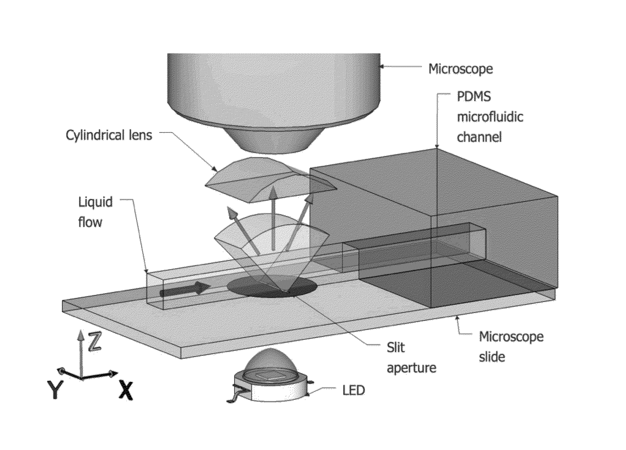
[0022]The disclosed modifications relate to imaging in optofluidic microscopes (OFM) using a fluid channel. A typical OFM includes three basic parts: an illumination source, a fluid system, and an image detector. The illumination system may use a variety of sources such as sunlight, lasers and LEDs. The detector is typically a CCD sensor although other sensors may be used. The fluid system includes a channel that is etched into a transparent substrate, such as PDMS, which may be bonded directly to the CCD. Input and output ports are then added to the channel to ensure a fluid flow across it.

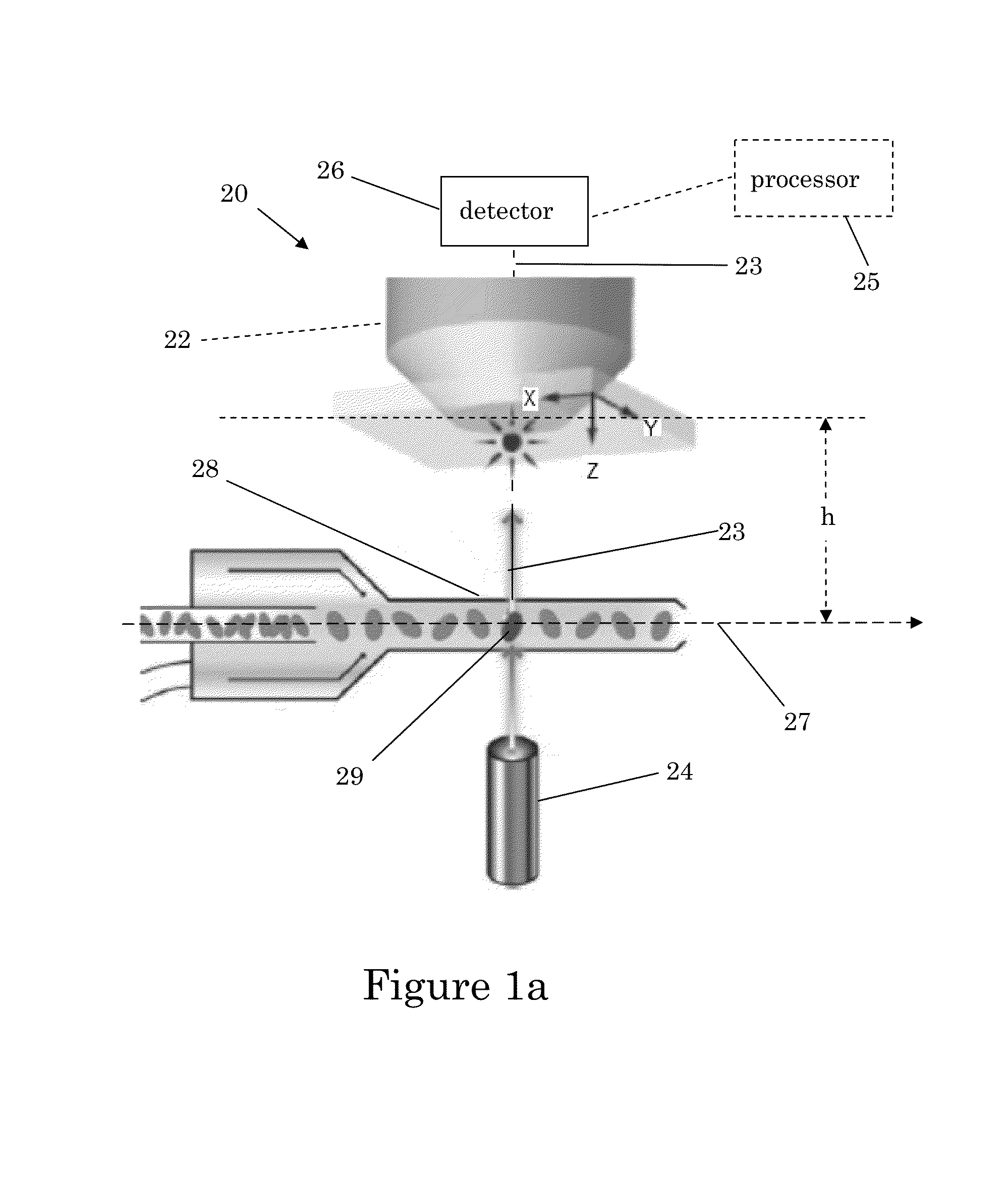
[0023]FIG. 1a shows a schematic block diagram of an OFM 20. It should be understood that such microscopes may include additional features that are not shown such as a stage, revolving nosepiece with multiple objective lenses, condenser lens, iris, coarse and fine focus and the like. Such aspects are well known in the art. The OFM 20 includes a light source 24 and a detector 26. The OFM 20 may opt...


PUM


Abstract

A microscope is disclosed, the microscope having a light source defining an optical axis along a Z direction and a detector disposed in X-Y direction, orthogonal to the optical axis, the detector configured to capture images of an object. The microscope includes a fluid channel having an inlet and an outlet configured with a fluid flow to transport the object from the inlet to the outlet. The detector is configured to capture a plurality of images of the object as the object moves from the inlet to the outlet. The plurality of images of the object may have different heights of the sample with respect to the detector as the sample flows through the channel. The channel may be tilted with respect to the optical axis. The detector may be tilted with respect to the optical axis.

Description

CROSS-REFERENCE TO PRIOR FILED APPLICATIONS[0001]This application claims priority to U.S. provisional application 61 / 699,020 which was filed on Sep. 10, 2012 and U.S. provisional application 61 / 699,003 which was filed on Sep. 10, 2012 both of which are incorporated herein in their entirety.TECHNICAL FIELD[0002]This invention relates generally to optofluidic microscopes (OFM) and modifications to OFMs.BACKGROUND[0003]Optofluidic microscopes allow imaging of small objects, typically cells, that travel through a fluid channel. There are two types of optofluidic microscopes: those that image only intensity and those that use interference (holography) to record both intensity and phase. The former method is the simplest but lacks key information, while the latter requires additional beams and optical paths. To date, both methods measure only a 2D surface and are limited to imaging structures whose size is larger than a wavelength. Improvements in optofluidic microscope systems would be d...

Claims


Application Information

Patent Timeline
IPC IPC(8): G01N21/59
CPCG01N21/59G01N15/1434G02B21/367G01N2015/1445G01N15/1475G02B21/086G01N15/1463B01L3/50G02B21/0004G01N2015/1006G01N15/147B01L3/502715
Inventor FLEISCHER, JASON, W.
Owner THE TRUSTEES FOR PRINCETON UNIV
Why Eureka
Try Eureka