Unlock instant, AI-driven research and patent intelligence for your innovation.
Protective cover for a tablet computer
What is Al technical title?
Al technical title is built by PatSnap Al team. It summarizes the technical point description of the patent document.
a tablet computer and protective cover technology, applied in the field of tablet computers, can solve the problems of cumbersome and less efficient word processing on the touch-screen keyboard, not providing all the functionality of a more robust computing device, and reducing the efficiency of word processing, so as to reduce increase and reduce the effect of the retention strength of the slo
Active Publication Date: 2014-03-13
LOGITECH EURO SA
View PDF5 Cites 9 Cited by
Summary
Abstract
Description
Claims
Application Information
AI Technical Summary
This helps you quickly interpret patents by identifying the three key elements:
Problems solved by technology
Method used
Benefits of technology
Benefits of technology
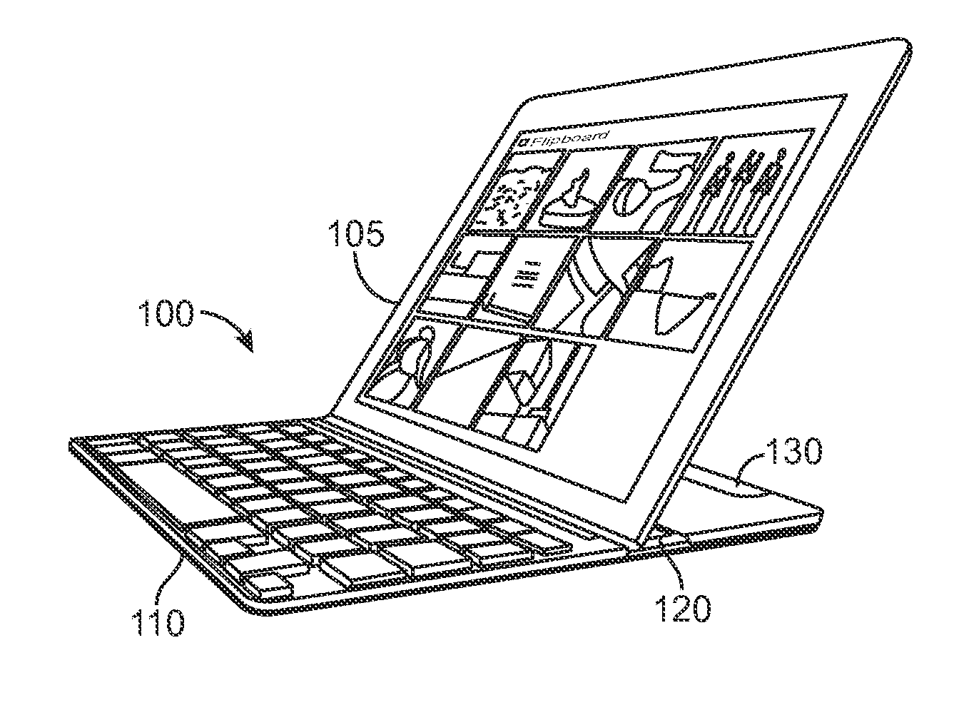
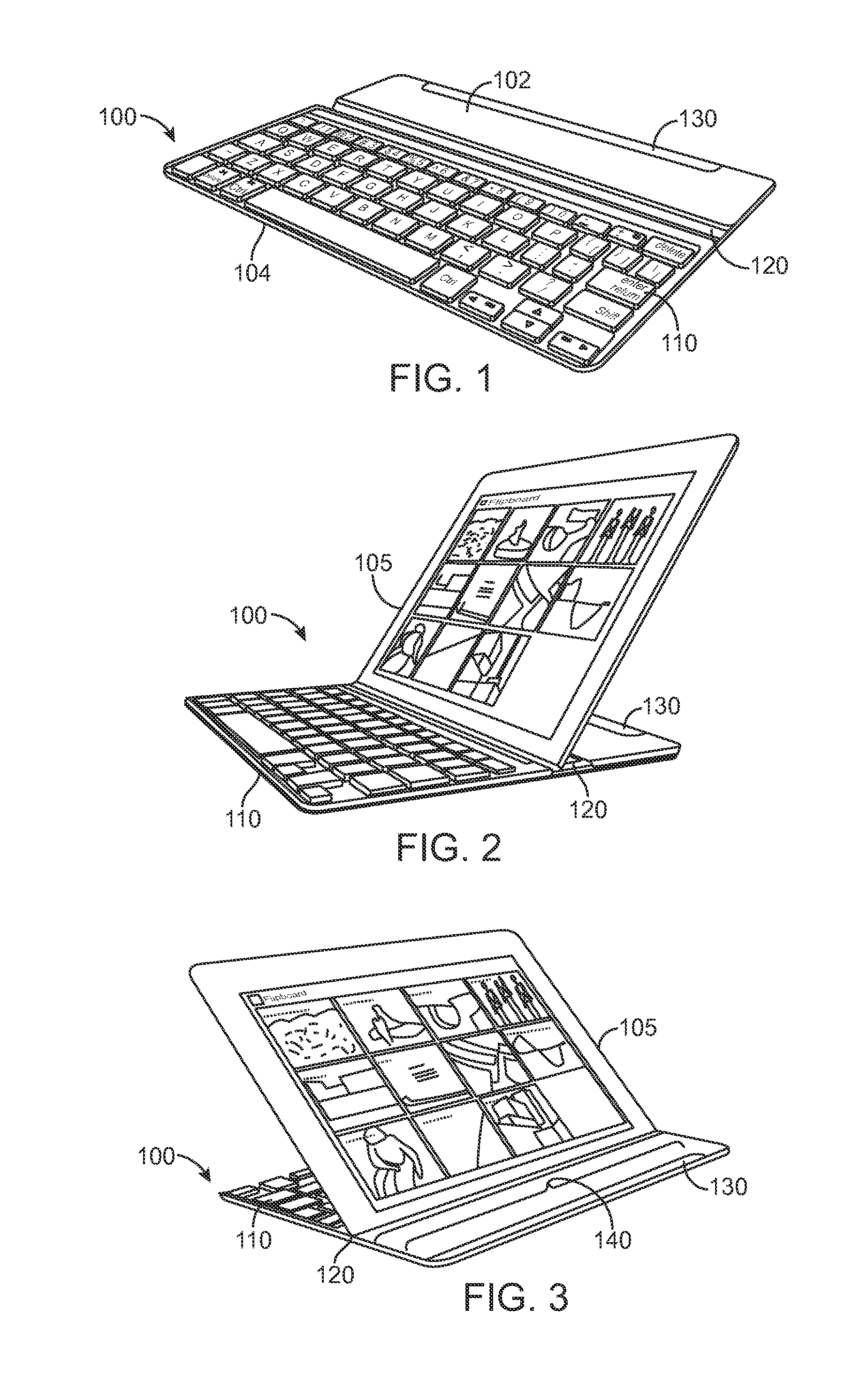
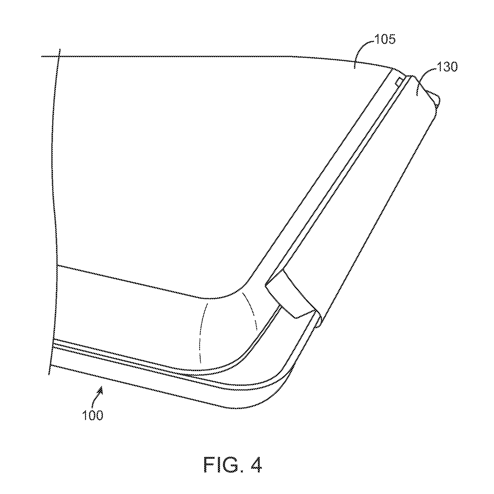
The patent describes an apparatus and protective cover for holding an input device in an upright configuration. The slot in the housing can hold the input device in multiple configurations, including a forward-facing and backward-facing upright configuration. The slot can be molded with a rubber compound to improve the hold strength of the input device and reduce slippage. Magnets can also be added to increase the retention strength of the slot. The protective cover includes a housing with a front and back portion and a slot spanning the width of the housing. Overall, the patent provides a solution for holding input devices securely in upright configurations.
Problems solved by technology
However, the portability of the tablet computer introduces some disadvantages as it may not provide all the functionality of a more robust computing device, such as a laptop.
For example, performing word processing on a touch-screen keyboard may be cumbersome and less efficient.
Method used
Image
Click on the blue label to locate the original text in one second.
Reading with bidirectional positioning of images and text.
Examples
Embodiment Construction
[0057]Embodiments of the invention are directed to a protective cover for a computing device. The protective cover may include a latch configured to translate from the protective cover in a horizontal or diagonal manner. The protective cover may include a hinge with a stopper preventing over rotation of the hinge. The protective cover may include a sliding tray that allows for the computing device to engage into a slot in the protective cover in a plurality of configurations. In some embodiments, the slot is configured with a switch that when activated by a computing device contacting the switch, places the keyboard in the protective cover into a pre-defined mode of operation. The protective cover may house magnets in a plurality of locations and configurations that allow the protective cover and the computing device housed by the protective cover to be oriented in a plurality of formations. A keyboard in the protective cover may be configured with a specific layout of keys and the ...
PUM
Property
Measurement
Unit
angle
aaaaa
aaaaa
angle
aaaaa
aaaaa
threshold angle
aaaaa
aaaaa
Abstract
Aspects of the invention relate to an apparatus including a housing and a slot disposed in the housing, the slot configured to hold an input device in a plurality of upright configurations including at least a forward-facing upright configuration such that the input device faces the front portion of the housing, and at least a backward-facing upright configuration such that the input device faces the back portion of the housing. The slot can be overmolded with a rubber compound (e.g. silicon-based) and configured to provide an improved coefficient of friction to reduce slippage of the input device when held in the slot. In some aspects, the housing includes a surface, and the overmolded portion of the slot can protrude above the surface of the housing.
Description
CROSS-REFERENCES TO RELATED APPLICATIONS[0001]The present non-provisional application claims benefit under 35 U.S.C. §120 of U.S. Provisional Patent Application No. 61 / 699,856, filed on Sep. 11, 2012, and entitled “Protective Cover for a Mobile Input Device,” and U.S. Provisional Patent Application No. 61 / 800,850, filed on Mar. 15, 2013, and entitled “Protective Cover for a Tablet,” both of which are incorporated by reference in their entirety for all purposes.[0002]The following non-provisional U.S. patent applications (including this one) are being filed concurrently, and the entire disclosure of the other applications are incorporated by reference into this application in their entirety for all purposes:[0003]application Ser. No. 13 / ______, filed Mar. 29, 2013 (Attorney Docket No. 86947-870543-099860US);[0004]application Ser. No. 13 / ______, filed Mar. 29, 2013 (Attorney Docket No. 86947-870544-099870US); and[0005]application Ser. No. 13 / ______, filed Mar. 29, 2013 (Attorney Docke...
Claims
Application Information
Patent Timeline
Application Date:The date an application was filed.
Publication Date:The date a patent or application was officially published.
First Publication Date:The earliest publication date of a patent with the same application number.
Issue Date:Publication date of the patent grant document.
PCT Entry Date:The Entry date of PCT National Phase.
Estimated Expiry Date:The statutory expiry date of a patent right according to the Patent Law, and it is the longest term of protection that the patent right can achieve without the termination of the patent right due to other reasons(Term extension factor has been taken into account ).
Invalid Date:Actual expiry date is based on effective date or publication date of legal transaction data of invalid patent.
Patent Type & Authority Applications(United States)
